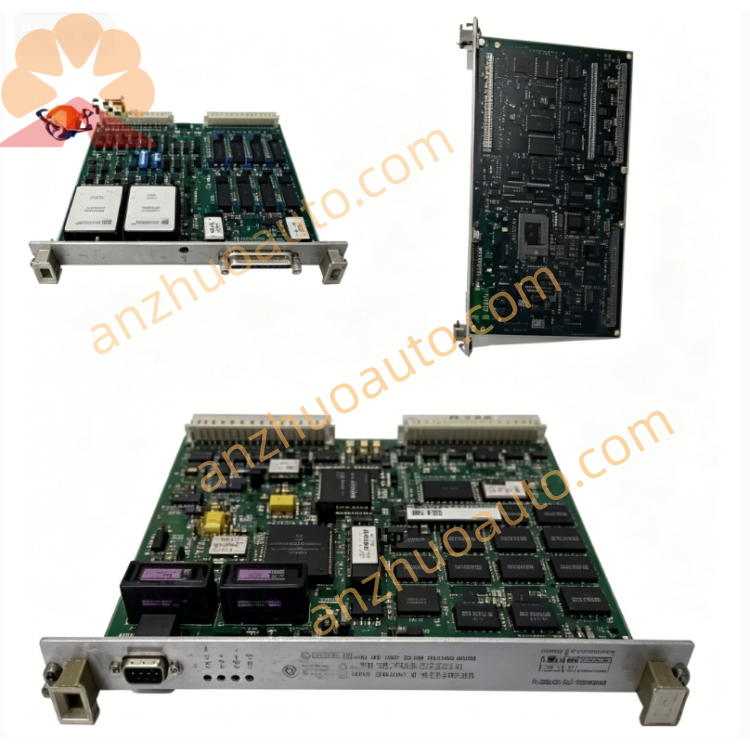
GE VME-6500-000000 6U VME Multifunction Analog & Digital I/O Board
Description
1. Product Overview
2. Core Technical Specifications
Mechanical & Bus Configuration
Standard Size: 6U VME industrial chassis, multi-slot VME backplane
Backplane Bus: Compliant with VME64 industrial bus standard, gold-plated slot connectors
Supported Modules: All GE Mark VI/VIe series VME single-slot / dual-slot boards, PMC expansion cards
Structure Material: High-strength aluminum alloy frame, galvanized anti-rust metal shell
Cooling & Protection Performance
Built-in high-reliability DC cooling fans with over-temperature alarm output
Full surrounding EMI shielding for anti-electromagnetic interference
Integrated internal temperature sensor for real-time cabinet temperature monitoring
Power Distribution Parameters
Supports wide-range external DC power input, internal multi-channel stabilized DC output for VME modules
Built-in overvoltage, overcurrent, short-circuit and reverse connection protection for each power branch
Environmental & Safety Ratings
Operating Temperature: 0℃ ~ +60℃
Storage Temperature: -30℃ ~ +70℃
Relative Humidity: 10%–95% RH, non-condensing
Hazardous Location Certification: Class I Division 2
Protection Class: IP20 (for indoor control cabinet installation)
Mechanical Installation
Two installation modes: cabinet embedded mounting / floor stand support mounting
Reserved cable management brackets and wire-through holes on left and right sides
Warranty: 12-month factory warranty for brand-new VME-6500-000000 chassis
3. Chassis Internal & External Structure Description
Front Area
Multi-position VME card slot openings with locking screw reserved holes for each module
Fan running status indicator light and over-temperature alarm signal terminal
Front door with transparent dust-proof window, quick-release lock for easy module maintenance
Rear Area
External DC power input terminal block with positive/negative polarity marking
Signal wiring cable outlet holes with rubber anti-abrasion sealing rings
External alarm signal output terminals for connecting cabinet HMI alarm system
Internal Layout
Central VME gold-plated backplane, independent power distribution area on the bottom layer
Side forced air cooling fans and directional ventilation air ducts for uniform heat dissipation
Metal shielding partitions separating power area and signal bus area to reduce interference
Auxiliary Accessories
Module fixing screws, cable binding brackets, dust filter cotton for fan air inlet
4. Standard Installation Operating Procedures
Connect external DC power supply cable to rear power input terminal, strictly distinguish positive and negative poles, tighten terminal screws;
Lead all module external signal cables out through rear wire-through holes, install rubber sealing rings to prevent dust and moisture from entering the chassis;
Connect over-temperature alarm signal cable to rear alarm terminals and link to upper monitoring alarm system.
Step 4 Module Insertion Sequence
Insert heavy heat-generating boards (UCVD main control, S200 DSP) into middle slots close to cooling fans for priority heat dissipation;
Install I/O termination boards, communication PMC cards and servo signal boards in remaining slots one by one, tighten front panel locking screws for each module;
Reserve 1–2 empty slots as maintenance spare positions.
Step 5 Pre-Power-On Comprehensive Inspection
Check all power terminals without short circuit, all VME modules fully inserted into backplane slots, fan air inlet filter cotton installed intact without blockage. Confirm no metal debris left inside the chassis before power supply switching on.
Step 6 Power-On Commissioning & Acceptance
Switch on external DC power supply. Observe fan run indicator light steady on, no over-temperature alarm output. Insert all control modules and complete system communication test; verify all boards obtain stable bus power and normal data interaction. Installation acceptance is passed after chassis temperature remains stable under full-load continuous operation.
5. Daily Operation & Regular Maintenance Standards
Normal Operation Judgment Standard
Cooling fans run smoothly without abnormal noise; chassis temperature maintains within 0~60℃ without over-temperature alarm; all VME modules operate normally without bus communication failure.
Regular Inspection Checklist
Shift Inspection: Check fan running indicator, confirm no over-temperature alarm signal output;
Monthly Maintenance: Take out fan filter cotton and clean dust with compressed air blower; check fan rotation smoothness;
Quarterly Inspection: Retighten rear power and signal wiring terminals, clean dust on VME backplane connectors, inspect shell anti-corrosion coating integrity.
Environmental Maintenance
Keep the outer control cabinet fully sealed and equipped with dehumidifier, avoid corrosive gas, conductive dust and water vapor entering the VME chassis interior.
6. Common Fault Diagnosis & Troubleshooting
7. Mandatory Safety Operation Precautions
Cut off external DC input power of the entire chassis before opening front door, disassembling modules or maintaining internal wiring, to avoid electric shock and system bus short-circuit risk.
Only matched GE original VME modules and certified shielded cables are allowed to be installed and wired inside the chassis; non-standard accessories will cause bus communication failure and void warranty.
Stop turbine control system operation immediately and cut off chassis power supply if over-temperature alarm cannot be eliminated; long-term high temperature will cause permanent burnout of all internal control boards.
Unauthorized disassembly of chassis metal shielding frame and internal backplane components is prohibited; damage caused by private disassembly is not covered by warranty.
Adopt shockproof and dust-proof packaging during transportation and storage; avoid heavy collision and extrusion to prevent backplane connector deformation.
This chassis carries turbine safety critical control hardware. All internal module replacement, wiring and maintenance must be operated by certified GE industrial control technicians with turbine safety qualification.
Get a Quote