GE IS230STAI2ASRTD2AH01 STAI RTD Temperature Analog Input Module for Mark VIe Turbine Control System
Description
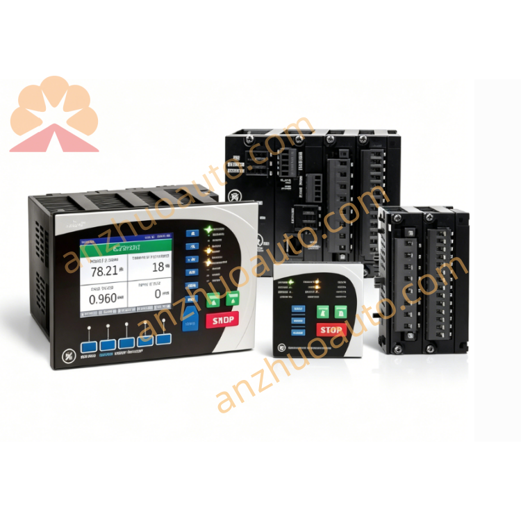
1. Product Overview
2. Core Technical Specifications
Signal Channel & Supported Sensors
Multi-channel dedicated RTD temperature input terminals
Compatible with 2-wire, 3-wire, 4-wire PT100 platinum resistance temperature sensors
Built-in line resistance automatic compensation circuit for long-distance field wiring
Independent channel reinforced electrical isolation
Communication & Diagnosis
Mark VIe high-speed VME backplane bus for bidirectional data interaction with UCVD main control board
Front panel integrated LED indicator array: Power, Run, Global Fault and single-channel abnormal alarm lights
Hardware self-diagnosis: RTD open circuit, short circuit, signal overload, backplane communication loss
Hot-swap support, no full rack power cut required for single module replacement
Electrical Parameters
Operating Power: 18–36 VDC wide-range DC input supplied by VME rack backplane
Integrated overvoltage, overcurrent and reverse polarity protection circuit for all channels
Environmental & Safety Ratings
Operating Temperature: -30℃ ~ +65℃
Storage Temperature: -40℃ ~ +70℃
Relative Humidity: 10%–95% RH, non-condensing
Hazardous Location Certification: Class I Division 2
PCB Protection: Full-board anti-moisture, anti-corrosion conformal coating
Protection Grade: IP20, only for sealed cabinet internal installation
Mechanical Specifications
Mounting Method: Standard single-slot VME rack insertion
Industrial reinforced anti-vibration PCB layout
Origin: Salem, Virginia, USA
Warranty: 12-month full factory warranty for brand-new original IS230STAI2ASRTD2AH01 modules
3. Front Panel & Terminal Functional Description
LED Diagnostic Indicator Zone
Power LED: Solid green = normal power supply; Off = power interruption or reversed polarity
Run LED: Slow green flicker = normal RTD signal acquisition and bus transmission; Fast flicker = firmware upgrading in progress
Fault LED: Solid red = fatal module hardware failure; Amber flash = single RTD channel open/short circuit or temperature out-of-limit warning
Channel Status LEDs: Light on = corresponding RTD channel normal signal collection; Light off = channel no valid signal input
Numbered Spring Terminal Block
Multi-group self-locking wiring terminals for PT100 RTD sensor cables, clear channel serial number marking, reserved wiring space for 2/3/4-wire sensor connection
Panel Locking Screws
Two fixed screws on left and right sides of front panel, used to lock module tightly in VME slots to prevent displacement caused by unit operation vibration
4. Standard Installation Operating Procedures
The module obtains DC operating power through VME backplane, no independent power wiring needed.
Connect on-site PT100 RTD sensor cables to corresponding numbered channel terminals, distinguish 2/3/4-wire wiring modes strictly according to field sensor type, fully tighten all spring terminal screws.
Ensure no short circuit between signal lines and ground wire, reduce long-distance wiring electromagnetic interference.
Step 4 Pre-Power-On Comprehensive Inspection
Check all terminal wiring tightness, confirm no exposed wire cores, inter-channel short circuit or extruded damaged cables. Only GE certified shielded RTD dedicated signal cables can be used for field wiring.
Step 5 Power-On Commissioning & Acceptance
Energize the entire Mark VIe control rack. Verify Power LED keeps solid green, Run LED flickers slowly without persistent red fault alarm. Check temperature value displayed on turbine HMI matches actual measuring point temperature; installation acceptance is completed after all RTD channels collect temperature data accurately and stably.
5. Daily Operation & Regular Maintenance Standards
Normal Operation Judgment Standard
All front panel LEDs maintain normal operating states without continuous red fault alarms; turbine upper monitoring HMI shows no RTD sensor open/short circuit, temperature signal loss or measurement drift alarms.
Regular Inspection Checklist
Shift Inspection: Record LED indicator status and abnormal channel fault codes in daily operation log;
Monthly Maintenance: Blow dust on module ventilation gaps and terminal blocks with dry compressed air blower;
Quarterly Inspection: Retighten all RTD signal wiring terminals, inspect cable aging and metal terminal oxidation.
Cabinet Environmental Maintenance
Keep control cabinet fully sealed with continuous dehumidifier operation to maintain low internal humidity; isolate corrosive gas, conductive metal dust and water vapor from module installation area to guarantee long-term temperature measurement precision.
6. Common Fault Diagnosis & Troubleshooting
7. Mandatory Safety Operation Precautions
Cut off the entire VME rack DC power supply before wiring, disassembly and maintenance work. Although the module supports hot-swap, power-off overhaul is recommended to prevent temperature signal surges from interfering with turbine safety overheat protection loops.
Only original GE certified shielded RTD dedicated signal cables are allowed for field wiring; uncertified third-party cables will cause severe temperature measurement drift and void the official factory warranty.
Immediately suspend temperature signal acquisition and start cabinet cooling equipment when operating ambient temperature exceeds 65℃; long-term over-temperature leads to irreversible burnout of high-precision AD conversion chips.
Unauthorized disassembly of module housing and internal precision circuit components is strictly prohibited; hardware damage caused by private disassembly is not covered under warranty terms.
Anti-static and shockproof dedicated packaging must be adopted for product transportation and storage; avoid heavy collision, extrusion and static discharge to protect internal high-precision temperature processing chips.
This RTD temperature input module participates in turbine bearing, cylinder and generator overheat safety interlock control loops. All replacement, firmware debugging and fault maintenance operations must be completed by certified GE industrial control professional technicians with turbine safety operation qualification.
Get a Quote