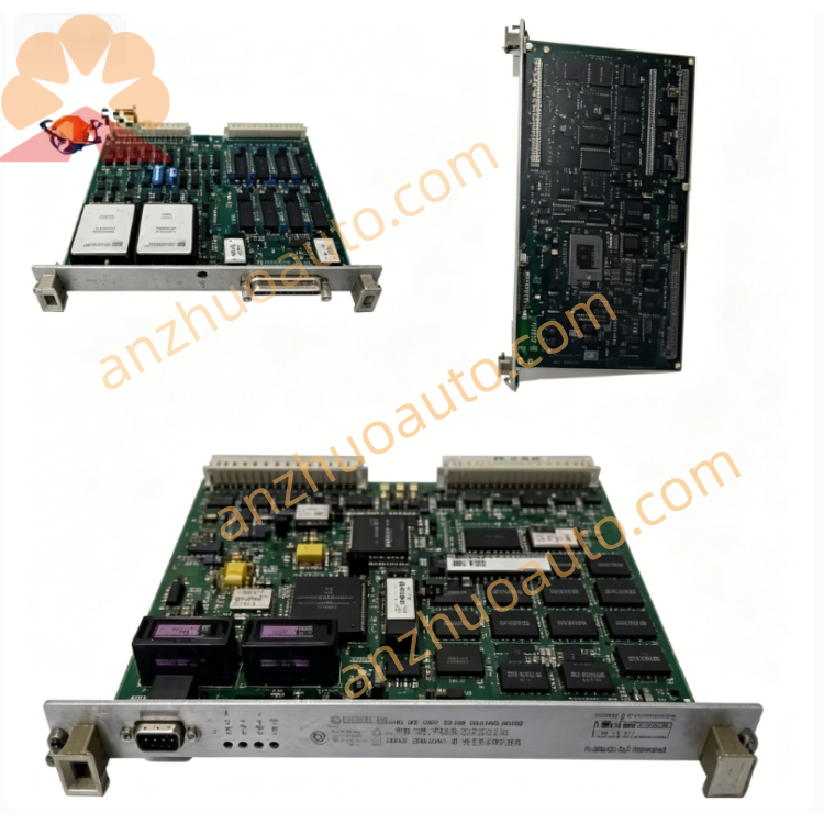
GE IS220PAICH1 PAIC High Density Analog Input Module for Mark VIe Speedtronic Turbine Control System
Description
1. Product Overview
2. Core Technical Specifications
Signal Channel Configuration
High-density multi-channel analog input terminals
Supported signal types: 4–20mA loop current, 0–10VDC voltage analog signals
Independent channel electrical isolation circuit
Communication & Diagnosis
Mark VIe high-speed internal backplane bus for data exchange with main controller
Front panel LED array for power, running state, fault and channel abnormality diagnosis
Hardware real-time self-test for channel open circuit, short circuit and signal overload
Hot-swap compatible without full rack power cut
Electrical Parameters
Operating Power: 18–36 VDC wide-range DC power input
Built-in channel surge, overvoltage and reverse polarity protection
Environmental & Safety Ratings
Operating Temperature: -30℃ ~ +65℃
Storage Temperature: -40℃ ~ +70℃
Relative Humidity: 10%–95% RH, non-condensing
Hazardous Location Certification: Class I Division 2
PCB Protection: Full-board anti-moisture, anti-corrosion conformal coating
Protection Class: IP20, cabinet internal installation only
Mechanical Specifications
Mounting Mode: Standard VME single-slot rack insertion
Industrial anti-vibration reinforced PCB layout
Origin: Salem, Virginia, USA
Warranty: 12-month factory original warranty for brand-new IS220PAICH1 modules
3. Front Panel & Terminal Functional Description
LED Diagnostic Indicator Zone
Power LED: Solid green = normal power supply; Off = power loss or reversed wiring polarity
Run LED: Slow green flicker = normal analog data collection and bus transmission; Fast flicker = firmware upgrade in progress
Fault LED: Solid red = fatal module hardware failure; Amber flash = single channel signal overload/open/short fault
Multi-Channel Analog Signal Terminal Block
Numbered spring locking terminals for field analog sensor wiring; independent channel separation design reduces signal crosstalk interference
VME Locking Screws
Two fixed screws on both sides of the front panel, used to lock the module tightly into VME rack slots and prevent displacement caused by unit vibration
4. Standard Installation Operating Procedures
Connect rack standard DC power supply to module internal power circuit via backplane;
Lead field 4–20mA / 0–10V analog sensor cables into corresponding numbered channel terminals and fasten all spring terminal screws tightly;
Double-check each channel wiring polarity to avoid reverse signal input damaging internal acquisition chips.
Step 4 Pre-Power-On Comprehensive Inspection
Check all terminal wiring tightness, confirm no wire stripping overlength, inter-channel short circuit or extruded damaged cables. Only GE factory certified shielded analog signal cables can be used for field wiring to suppress industrial electromagnetic interference.
Step 5 Power-On Commissioning & Acceptance
Energize the entire Mark VIe control rack. Verify Power LED stays solid green, Run LED flickers slowly and no red Fault alarm light is on. Check analog measurement values displayed on turbine HMI match actual field sensor readings; installation acceptance is passed after all channel acquisition indexes meet factory standards.
5. Daily Operation & Regular Maintenance Standards
Normal Operation Judgment Standard
All front panel LED indicators maintain normal operating states without persistent red fault alarms; turbine upper monitoring HMI shows no analog signal loss, channel overload or abnormal measurement drift alarms.
Regular Inspection Checklist
Shift Inspection: Record all LED status and abnormal channel alarm codes in daily operation log;
Monthly Maintenance: Blow dust on module ventilation gaps and terminal blocks with dry compressed air blower;
Quarterly Inspection: Retighten all analog signal wiring terminals, inspect cable aging and metal terminal oxidation.
Cabinet Environmental Maintenance
Keep control cabinet fully sealed with continuous dehumidifier operation to maintain low internal humidity; isolate corrosive gas, conductive metal dust and water vapor from module installation area to extend service life.
6. Common Fault Diagnosis & Troubleshooting
7. Mandatory Safety Operation Precautions
Cut off the entire VME rack DC power supply before wiring, disassembly and maintenance. Although the module supports hot-swap, power-off overhaul is recommended to prevent analog signal surges impacting the main controller safety loop.
Only original GE certified shielded analog signal cables are allowed for field wiring; uncertified third-party cables will cause severe measurement drift and void the official factory warranty.
Immediately stop analog signal acquisition and start cabinet cooling equipment when operating ambient temperature exceeds 65℃; long-term over-temperature leads to irreversible burnout of high-precision AD conversion chips.
Unauthorized disassembly of module housing and internal precision circuit components is strictly prohibited; hardware damage caused by private disassembly is not covered under warranty terms.
Anti-static and shockproof dedicated packaging must be adopted for product transportation and storage; avoid heavy collision, extrusion and static discharge to protect internal high-precision signal processing chips.
This analog input module participates in turbine closed-loop regulation and safety interlock control loops. All replacement, firmware debugging and fault maintenance operations must be completed by certified GE industrial control professional technicians with turbine safety operation qualification.
Get a Quote