GE IS215WETAH1BB WETA Topbox B Ethernet I/O Communication Module for Mark VI & Mark VIe Turbine Control System
Description
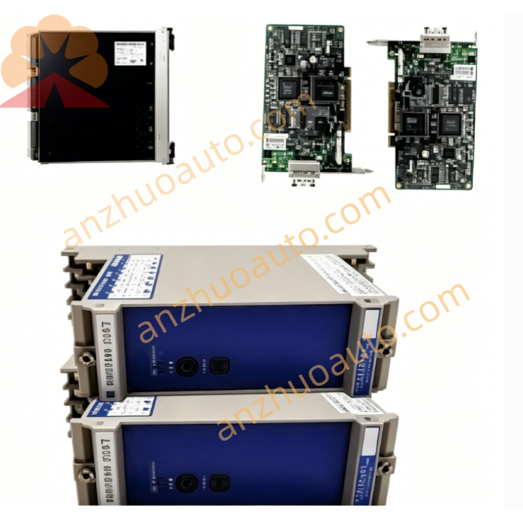
1. Product Overview
2. Core Technical Specifications
Communication Interfaces
Mark VIe high-speed backplane internal bus for data interaction with rack main controller
Front industrial Ethernet RJ45 port for on-site debugging and auxiliary monitoring
Multi-channel spring terminal blocks for field digital input and output wiring
Signal Processing Performance
Reinforced electrical isolation for all signal channels
Multi-stage digital filtering to suppress strong electromagnetic interference
Real-time hardware self-diagnosis for channel open circuit, short circuit and communication failure
Hot-swap maintenance support without shutting down the whole control system
Electrical Parameters
Operating Power: 18–36 VDC wide-range DC input
Integrated overvoltage, overcurrent and reverse polarity protection circuit
Environmental & Safety Standards
Operating Temperature: -30℃ ~ +65℃
Storage Temperature: -40℃ ~ +70℃
Relative Humidity: 10%–95% RH, non-condensing
Hazardous Certification: Class I Division 2
PCB Protection: Full-board anti-moisture, anti-corrosion conformal coating
Protection Grade: IP20, for internal cabinet installation only
Mechanical Specifications
Mounting Method: Standard 35mm DIN rail installation
Anti-vibration industrial PCB layout
Origin: Salem, Virginia, USA
Warranty: 12-month factory original warranty for brand-new modules
3. Front Panel & Terminal Layout Description
LED Diagnostic Indicator Area
Power LED: Solid green = normal power supply; Off = power loss or reversed wiring polarity
Run LED: Slow green flicker = normal data transmission; Fast flicker = firmware upgrade in progress
Fault LED: Solid red = severe hardware or channel fault; Amber flash = minor signal abnormal warning
Ethernet Link LED: Green flicker = normal Ethernet communication; Off = Ethernet connection disconnected
Ethernet RJ45 Port
Connect portable debugging equipment, local touch screen or auxiliary monitoring host to export fault logs and modify module operating parameters offline
Multi-Position Spring Terminal Blocks
Two groups of numbered wiring terminals for field digital input and output signal cables, spring locking design to prevent loose contact caused by vibration
DIN Rail Locking Buckle
Elastic buckle at the bottom of the module, used to fix the module firmly on the DIN rail and avoid sliding during mechanical vibration
4. Standard Installation Steps
Connect 24VDC control power cable to the power terminal, strictly distinguish positive and negative poles to avoid reverse connection damage;
Route field digital input and output signal cables to corresponding numbered channel terminals and fasten spring screws;
Insert shielded Ethernet cable into the front RJ45 port if local debugging or auxiliary monitoring is required;
Insert the module into the Mark VIe rack backplane slot to complete internal communication connection with the main controller.
Step 4 Pre-Power-On Inspection
Check all terminals for tight wiring, confirm no over-exposed wire cores, short circuits or extruded damaged cables. Only GE certified shielded signal cables can be used for field wiring to reduce electromagnetic interference.
Step 5 Power-On Commissioning
Supply rated DC power to the module and the entire Mark VI/VIe control system. Confirm Power LED stays solid green, Run LED flickers slowly and Ethernet Link LED flashes periodically. Use debugging equipment via Ethernet to verify signal collection and control output response; installation acceptance is completed when all technical indicators meet standards.
5. Daily Operation & Maintenance Rules
Normal Operation Standard
All front panel LEDs maintain normal operating states without persistent red fault alarms; the upper monitoring HMI of turbines or wind farms displays no signal loss, channel short/open circuit or communication disconnection alarms.
Regular Inspection Checklist
Shift Inspection: Record LED indicator status and abnormal alarm information in the operation log;
Monthly Maintenance: Blow dust on ventilation gaps and terminal blocks with dry compressed air blower;
Quarterly Inspection: Retighten all power and signal wiring terminals, check cable aging and terminal oxidation.
Environmental Maintenance
Keep the control cabinet fully sealed and run the dehumidifier continuously to maintain low internal humidity; isolate corrosive gas, conductive dust and water vapor from the module installation area.
6. Common Fault Diagnosis & Troubleshooting
7. Mandatory Safety Precautions
Cut off the module DC power supply before wiring, disassembly and maintenance. Although the module supports hot-swap, power-off operation is recommended for long-term maintenance to prevent signal surges from impacting the main controller.
Only original GE matched shielded signal cables and Ethernet cables are allowed for wiring; uncertified third-party cables will cause severe communication interference and void the factory warranty.
Immediately stop field signal collection and start cabinet cooling equipment when the operating ambient temperature exceeds 65℃; long-term over-temperature will cause irreversible damage to internal signal isolation circuits.
Unauthorized disassembly of the module housing and internal circuit components is prohibited; hardware damage caused by private disassembly is not covered by the warranty.
Use anti-static and shockproof packaging for transportation and storage; avoid heavy collision, extrusion and static discharge to protect internal precision signal processing chips.
This module participates in wind turbine and turbine safety control loops. All replacement, firmware debugging and fault maintenance work must be operated by certified GE industrial control technicians.
Get a Quote