Instruction Manual
Model: IS215PMVDH1A
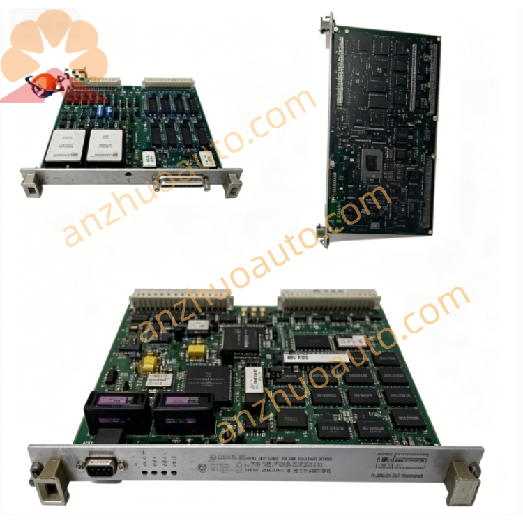
Product Name: Migration I/O Termination Module
Manufacturer: General Electric
Applicable System: Mark VI / Mark VIe Speedtronic Turbine Control System
Document Reference: GEH721 Official Manual
1. Product Overview
IS215PMVDH1A PMVD series H1A variant migration I/O termination module is a key peripheral component of GE heavy-duty turbine control platform. Its core function is centralized termination, isolation and transmission of field digital switching signals, realizing bidirectional data interaction between rack main control boards and on-site equipment without signal crosstalk. It supports signal migration and compatible replacement of old Mark VI hardware, greatly reducing system upgrade transformation costs. Integrated infrared diagnosis interface enables offline parameter configuration and bottom-layer fault reading without external upper computer wiring. Passive heat dissipation metal shell and anti-vibration circuit layout ensure long-term continuous operation in high-temperature, dusty industrial cabinet environments.
2. Core Technical Specifications
Signal Channel Configuration
Digital Contact Input: 96 channels
Relay Contact Output: 60 channels
Matching Accessories: JPDV interface board, DTBA/DTBB/DTBD/DTBC terminal boards
Communication & Diagnosis
Dual 100Mbps ARCNET/Ethernet communication bus
Front panel multi-group LED indicators: Power, Attention, Link, Activity
Built-in infrared diagnostic port for local parameter setting & fault detection
Electrical Parameters
Input Power: 18–36 VDC, max power consumption 12W
Isolation Voltage: Industrial grade reinforced signal isolation
Environmental Rating
Operating Temperature: -30℃ ~ +65℃
Storage Temperature: -40℃ ~ +70℃
Relative Humidity: 10%–95%, non-condensing
Hazardous Area Certification: Class 1 Div.2
Mechanical Structure
Installation: Standard VME dual-slot cabinet rack mounting, triple redundant parallel installation supported
Heat Dissipation: Side ventilation grille, fanless passive cooling
Net Weight: Approx. 0.6kg
Origin: Salem, Virginia, USA
Warranty: 12-month factory warranty for brand-new original modules
3. Front Panel Structure Description
LED Indicator Area
Power LED: Solid green = normal power supply; off = power failure
Attention LED: Amber flashing = minor warning; solid red = critical hardware fault
Link/Activity LED: Green flicker = normal data transmission; steady off = communication disconnection
Infrared Diagnostic Window: Below indicator lights, used with dedicated handheld diagnostic tool for offline troubleshooting and address configuration
Communication Terminal Interface: ARCNET/Ethernet bus wiring terminals for rack internal bus connection
Fixed Locking Screws: Two positioning screws on rear edge for stable rack fixing against vibration
4. Step-by-Step Installation Guide
Step 1 Cabinet Preparations
Install standard GE VME control rack, reserve 2 adjacent slots for module installation; maintain ≥5cm ventilation space around the module to avoid heat accumulation. Confirm cabinet internal temperature does not exceed 60℃ during full-load operation.
Step 2 Module Insertion & Fixing
Align IS215PMVDH1A with VME slot guide rail, push the module fully into the rack until the front panel fits tightly; tighten two rear locking screws to prevent sliding under mechanical vibration. Multiple modules can be installed side by side for triple redundant control configuration.
Step 3 Signal Wiring Sequence
Connect module internal bus cable to JPDV interface PCB inside the rack;
Match corresponding DT series terminal boards and connect field sensor/actuator contact signal lines;
Access 24VDC industrial control power supply to module power terminal, strictly distinguish positive and negative poles to avoid reverse connection damage.
Step 4 Pre-Power-On Inspection
Check all wiring tightness, confirm no short circuit, wire extrusion or aging damage; shielded industrial signal cables must be used for field wiring to suppress electromagnetic interference.
Step 5 Power-On Commissioning
Supply rated DC power to the whole Mark VI system; observe Power LED keep solid green, Link LED flicker normally. Use infrared diagnostic tool to read module address and channel status to complete installation acceptance.
5. Daily Operation & Maintenance Rules
Normal Operating Standard
All LED indicators operate per specification, no continuous red fault alarm; turbine control signal channels have no open circuit, short circuit or signal loss alarm on HMI.
Regular Inspection Items
Shift Inspection: Check front panel LED status, record abnormal alarm records;
Monthly Maintenance: Clean ventilation grille dust with dry air blower to prevent heat dissipation blockage;
Quarterly Inspection: Tighten wiring terminals, inspect cable aging and connector oxidation;
Environmental Maintenance
Keep control cabinet sealed and dehumidified; prohibit corrosive gas, conductive dust and liquid water vapor from entering the module installation area.
6. Fault Diagnosis & Troubleshooting
Fault 1: Power LED always off
Possible Causes: DC power supply loss, reverse power connection, internal power circuit burnout
Solutions: Test cabinet 24VDC power output; rewire positive/negative poles correctly; replace module if internal circuit damaged.
Fault 2: Attention red LED steady on, system signal channel alarm
Possible Causes: Overloaded relay output channel, short circuit of field input line, module internal channel chip damage
Solutions: Disconnect field signal wiring one by one to locate short-circuit point; reduce output load current; replace defective module if internal hardware breakdown.
Fault 3: Link LED off, communication lost with main controller
Possible Causes: ARCNET/Ethernet bus cable loose, JPDV interface board fault, module communication chip failure
Solutions: Re-plug bus connectors; inspect and replace faulty JPDV board; test module communication via infrared port, replace module if communication circuit damaged.
Fault 4: Infrared diagnostic port unresponsive
Possible Causes: Covered by dust, handheld diagnostic tool mismatch, module bottom-layer program exception
Solutions: Wipe infrared window with clean soft cloth; use GE official dedicated diagnostic device; re-flash module firmware after power cycle.
7. Mandatory Safety Precautions
Cut off the entire rack DC power supply before any wiring, disassembly or maintenance work to avoid electric shock and bus signal breakdown.
Only original GE matched DT series terminal boards and shielded signal cables are allowed; third-party non-certified accessories are forbidden, which will void the warranty.
Do not operate the module when ambient temperature exceeds 65℃; immediately stop operation and start cabinet cooling equipment when over-temperature alarm triggers.
Unauthorized disassembly of the metal housing is prohibited; damage to internal circuit boards caused by private disassembly is not covered by factory warranty.
Transport and store with shockproof anti-static packaging; avoid heavy collision, extrusion and static electricity discharge to protect internal precision chips.
This product is used for critical turbine safety control loop; replacement and maintenance must be operated by certified GE industrial control technicians.
8. Long-Term Storage Requirements
Store the module in dry, ventilated warehouse with temperature range -40℃ ~ +70℃, relative humidity below 80%. Keep away from chemical corrosives, heavy pressure and mechanical impact. Modules stored over 6 months must complete full communication and channel function test before formal cabinet installation.
Credibility Description
Confirmed Information: IS215PMVDH1A belongs to GE Mark VI/VIe migration I/O termination module, 96DI+60DO channel configuration, JPDV matching interface board, front LED + infrared diagnosis, 18–36VDC power supply, -30~65℃ operating temperature, Class 1 Div.2 certification, VME dual-slot rack installation, American original production, 12-month standard warranty.
Information to Be Further Verified: Exact module external dimension size, single channel maximum load current, complete fault code list, detailed infrared diagnostic operation steps.
Get a Quote