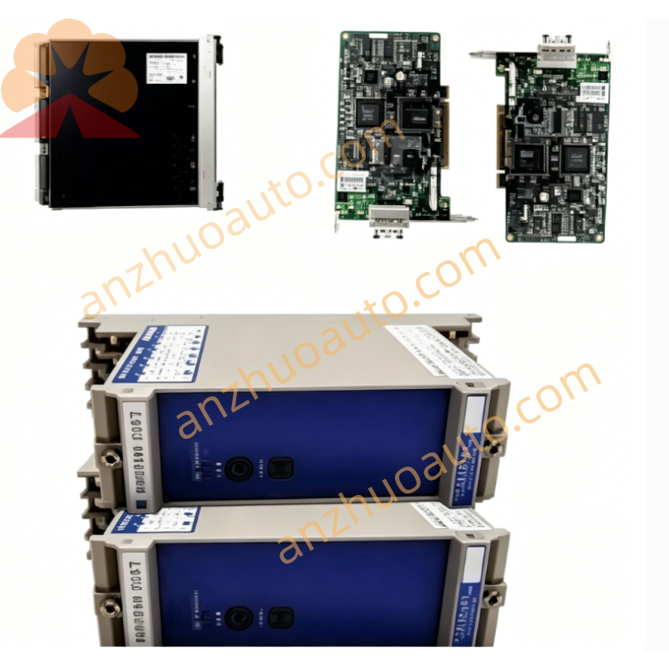
GE IS215ISBBH2A Splitter Communication Switch for Mark VI Turbine Control System
Description
Instruction Manual
1. Product Overview
2. Main Technical Specifications
Port Configuration: 3 RJ45 full-duplex Ethernet ports
P1: Full Duplex (with green plastic adapter)
P2: Transmit Out
P3: Receive In
Status Indicator: Single Receiver Active LED light
Working Ambient Condition
Operating Temperature: 0℃ ~ 45℃
Storage Temperature: -20℃ ~ 70℃
Relative Humidity: 10% ~ 95%, non-condensing
Mechanical Performance
Non-operating Shock Resistance: 10G
Mounting Method: Standard DIN-rail installation
Housing: Ventilated metal shell, heat dissipation design
Net Weight: Approx. 1.2KG
Origin: Salem, VA, USA
Warranty: 12-month standard factory warranty for new original unit
3. Hardware Structure Description
Front Panel: Equipped with one Receiver Active LED diagnostic lamp; light on means receiving channel is normal, light off indicates signal interruption or equipment fault.
Port End 1 (Single Port Side): P1 Full Duplex port matched with green positioning adapter, connected to main control unit communication bus.
Port End 2 (Dual Port Side): P2 Transmit Out port for uploading control signals to field devices; P3 Receive In port for collecting feedback signals from on-site sensors and actuators.
Ventilation Grooves: Surrounding ventilated slots for continuous heat dissipation during long-time continuous operation.
4. Installation Steps
Connect main Mark VI controller Ethernet cable to P1 Full Duplex port with green adapter.
Connect field equipment signal transmit cable to P2 Transmit Out port.
Connect field feedback signal receive cable to P3 Receive In port.
Step 4 Circuit Inspection: Check all Ethernet plug locking state, confirm no loose or poor contact; avoid cable extrusion and bending damage.
Step 5 Power On Test: Supply system rated power to Mark VI control system, observe Receiver Active LED light up steadily to complete normal startup.
5. Operation & Daily Maintenance
Normal Operation Standard: LED keeps constant bright, no flicker; turbine control network communication has no packet loss or delay alarm.
Daily Inspection Items
Check LED indicator status every shift
Clear dust on housing ventilation grooves monthly to avoid heat blockage
Inspect Ethernet cable aging and plug looseness quarterly
Environment Maintenance: Keep cabinet dry, avoid water vapor, corrosive gas and conductive dust entering the equipment.
6. Fault Diagnosis & Troubleshooting
Fault 1: Receiver Active LED always off
Possible Causes: P1 port loose wiring, main control bus signal loss, internal circuit damage
Solutions: Re-plug P1 Ethernet cable; test main controller communication output signal; replace unit if internal hardware fails.
Fault 2: System communication packet loss, LED flickers irregularly
Possible Causes: Cable aging, ambient temperature over 45℃, humidity condensation inside housing
Solutions: Replace intact industrial Ethernet cable; enhance cabinet cooling device; dehumidify control cabinet.
Fault 3: Equipment slips off DIN rail
Possible Causes: Fixing buckle not locked, rail deformation
Solutions: Re-lock bottom buckle; replace qualified standard DIN rail.
7. Safety Precautions
Cut off all system power supply before disassembly, wiring and maintenance to prevent electric shock and communication bus breakdown.
Do not use non-industrial ordinary Ethernet cables; only shielded anti-interference cables designated for Mark VI system are allowed.
Forbid using in environment exceeding rated temperature and humidity range; stop operation immediately when ambient temperature exceeds 50℃.
Do not disassemble metal housing without authorization; internal circuit damage caused by private disassembly is not covered by warranty.
Transport the product with shockproof packaging; avoid strong collision and extrusion to prevent internal board damage.
Get a Quote