GE IS215ACLEH1B High Density Analog Input Conditioner Module Compact Product Specification
1. Product General Overview
IS215ACLEH1B is a high-density universal analog signal conditioning PCB belonging to GE IS215 hardware series, exclusively developed for Mark VIe Speedtronic gas, steam and aeroderivative turbine integrated distributed control systems. This upgraded second-generation unit expands multi-sensor analog input density, strengthens long-distance field cable surge immunity, optimizes PCB thermal dissipation under full load and integrates factory pre-calibration with serialized traceability. The board accepts four mainstream industrial analog sensor signals: RTD, K/J/T thermocouple, 4–20mA DC loop current and 0–10V bipolar/unipolar voltage, delivering galvanic isolation, multi-order EMI filtering, precision gain amplification and impedance matching to convert weak field signals into standardized sampled data for main controllers. It fully supports simplex, dual redundant hot standby and TMR triple modular redundant safety racks, providing mass high-precision measurement data for turbine multi-point temperature distribution, distributed pressure monitoring, flow loop feedback and over-temperature safety protection logic.
Manufactured to GE aerospace-grade PCB production standards via fully automated SMT assembly, the entire printed circuit board is coated with reinforced conformal three-proof insulation coating to resist conductive industrial dust, mild-to-moderate corrosive process flue gas, high cabinet condensation and coastal salt fog oxidation, suitable for thermal power, petrochemical, LNG, offshore oil & gas and heavy industrial operating environments. Passive natural convection heat dissipation eliminates rotary cooling fans and mechanical wear components to reduce full lifecycle cabinet operation costs. A battery-free 1024-bit nonvolatile serial EEPROM is placed on an independent low-noise PCB partition, permanently storing IS215ACLEH1B hardware model ID, traceable serialized production numbers, full-channel factory-locked gain, linearity and temperature offset calibration datasets, multi-sensor configuration thresholds and hardware revision markers, with minimum 20-year stable data retention without external backup power supply. During rack power-on self-test, the Mark VIe main processor reads EEPROM metadata over the parallel backplane bus to complete automatic hardware topology matching; all preloaded channel sensor type and gain parameters synchronize instantly to CIMPLICITY HMI monitoring software, eliminating manual field calibration and parameter configuration during spare part replacement or cabinet upgrade reconstruction.
Compared with IS210-series analog conditioner boards, IS215ACLEH1B features higher channel density per single slot, upgraded multi-stage input transient voltage clamping for ultra-long field sensor cabling, enhanced low-frequency harmonic filtering for heavy rotating machinery interference, optimized wide copper trace layout for improved heat dissipation under continuous full dense sampling load and tightened component screening for high-humidity coastal/offshore sites. Each analog input channel adopts fully independent galvanic isolation loops to eliminate ground loop potential difference interference and lightning-induced transient overvoltage coupled through lengthy field wiring harnesses. Multi-tier self-recovery overvoltage, reverse polarity and overcurrent suppression circuits are embedded in each input branch to prevent irreversible damage to internal precision operational amplifiers caused by field wiring short-circuits, reversed sensor power supply and grid voltage transients. The module converts large batches of noisy multi-type field sensor signals into stable isolated standardized sampling data to support complex multi-point turbine safety protection, multi-variable closed-loop regulation and long-term mass process parameter trending logging.
2. Core Functional Operating Principles
2.1 Rack Parallel Bus Command and Logic Power Input Pre-Filter Circuit
IS215ACLEH1B receives analog channel configuration instructions and standardized +5V DC logic power supply from the Mark VIe main controller through the rear gold-plated multi-pin P1 backplane connector. All bus signal pins integrate composite high-frequency EMI filters and metal oxide varistor surge suppressors to attenuate electromagnetic noise generated by high-voltage switchgear switching, large motor startup transients and variable frequency drive operation, while dissipating transient overvoltage spike energy coupled from rack backplane wiring. Each bus pin is fitted with series current-limiting resistors and bidirectional TVS transient suppression diodes to contain surge energy and avoid breakdown of internal digital logic processing chips.
1500V AC dielectric withstand optocoupler isolation assemblies segregate the rack low-voltage logic bus domain and high-impedance field analog input domain, eliminating cross-talk interference between noisy bus power circuits and sensitive precision analog processing logic within a single rack slot. An on-board high-capacity data latch temporarily buffers all multi-channel analog sampling trigger commands, distributing sequential measurement instructions to each independent signal conditioning unit following system hardware priority protocols to prevent sampling data frame loss during simultaneous synchronous acquisition of dozens of dispersed field sensor signals. Standard DMA expansion pins including BAI bus acknowledge input, BAD bus acknowledge output and /EXT REO external DMA request pins are reserved on the P1 connector, enabling daisy-chained signal coordination with all other IS215-series discrete input, relay output and rack power supply boards, with maximum parallel bus transmission speed of 12 Mbps.
2.2 High-Density Multi-Channel Universal Analog Isolation & Conditioning Circuit
The PCB core signal front-end supports four standard industrial field sensor signal formats: RTD resistance temperature detectors, K/J/T-type thermocouples, 4–20mA passive loop current and ±10V / 0–10V DC voltage signals. IS215ACLEH1B integrates expanded fully separated analog input channels with independent dedicated wiring loops to eliminate cross-channel signal interference during synchronous mass multi-sensor sampling. Upgraded multi-order active RC low-pass filter assemblies are installed at each channel input front end to suppress power frequency harmonics and electromagnetic induction noise generated by ultra-long-distance field sensor cables, stabilizing long-term measurement linearity and precision under heavy industrial interference conditions.
The module supports software configurable signal type switching for each individual channel without hardware jumper modification, with factory pre-calibrated fixed gain ranges matched to mainstream industrial standard sensor output specifications. High-speed isolation signal transformers fully separate low-voltage internal precision analog circuits and high-impedance field sensor loops to block measurement distortion and component damage induced by ground potential discrepancies between cabinet control circuits and remote dispersed field measurement points. Single-channel analog signal sampling response delay is limited to ≤4ms to capture fast-changing turbine transient temperature and pressure fluctuation signals, ensuring timely closed-loop regulation adjustment and rapid over-limit protection trigger response. Each input channel embeds self-recovery overvoltage and reverse polarity protection; short-circuit or reversed wiring fault on one field sensor only locks the corresponding measurement channel, and all remaining analog input channels maintain continuous normal signal acquisition without full-board shutdown.
2.3 On-Board Hardware Identification and Factory Pre-Calibrated EEPROM Storage Circuit
A 1024-bit serial nonvolatile EEPROM chip is positioned on the upper right low-noise PCB partition, storing exclusive fixed hardware metadata unique to IS215ACLEH1B: official factory part number, batch traceable serialized production identifiers, factory-locked full-channel gain, temperature offset and linearity calibration test logs, bus timing matching parameters and hardware revision markers. All multi-sensor matching calibration data are permanently programmed at manufacturing, requiring no additional on-site calibration adjustment after field installation. No backup battery is required; all calibration and hardware identity data remain intact for over 20 years under the cabinet’s rated temperature and humidity operating range.
During rack power initialization self-inspection, the main control unit transmits serial reading commands through the P1 backplane bus to extract complete EEPROM data streams. The system automatically cross-references pre-stored channel signal configuration and gain data with preloaded cabinet topology files to verify hardware compatibility, synchronizing analog channel sensor type, measurement range and filter frequency definitions to the CIMPLICITY HMI monitoring platform without manual operator input. Every abnormal channel state including sensor open-circuit, input overvoltage protection trigger and bus communication loss is converted into timestamped digital fault codes, uploaded to the host permanent historical database for post-failure multi-point process parameter deviation analysis and hidden distributed measurement loop risk troubleshooting. A compact J2 auxiliary signal expansion connector fitted with a dust protection plug is reserved on the front panel side edge for supplementary field sensor wiring during customized cabinet function expansion and upgrade reconstruction projects.
2.4 Front Panel Status Indication Circuit
The matte black anti-corrosion aluminum alloy front panel is equipped with two universal green LED status indicators, each operating at a fixed 5mA constant current to reduce overall auxiliary power consumption. The PWR indicator maintains steady green illumination when the rack +5V logic power supplied to the module remains stable, and extinguishes instantly upon internal power circuit open-circuit or short-circuit faults. The DATA indicator stays continuously lit during uninterrupted bidirectional data communication between the rack main bus and all high-density analog conditioning channels; if bus disconnection, sampling command loss or channel amplifier circuit failure occurs, the DATA LED flashes at a fixed 1Hz cycle to deliver visible fault prompts observable through the cabinet door viewing window without external measuring instruments.
Independent miniature green LED indicators are allocated to every individual analog input channel. A channel LED lights steadily when valid analog sensor signals are detected within the normal calibrated measurement range, and turns off when sensor open-circuit or channel protection activation occurs. Field operators can directly judge the real-time operating state of all distributed field temperature, pressure and flow sensors via the front panel indicator layout, simplifying high-density multi-point analog measurement loop fault diagnosis work. No mechanical reset buttons or dedicated voltage test points are arranged on the front panel; the module is optimized for long-term unattended automatic mass analog signal sampling and conditioning without manual intervention operations. All LED indicator drive branches integrate independent series current-limiting resistors to prevent LED burnout after multi-year continuous cabinet operation.
2.5 Three-Tier Cascaded Full-Circuit Protection Architecture
Primary rack bus input protection: A miniature 0.5A slow-blow series fuse mounted on P1 connector power pins intercepts severe overcurrent surges originating from backplane wiring short-circuit faults.
Secondary analog input branch protection: Independent self-recovery current limiting circuits, reverse polarity blocking components and reinforced multi-stage transient voltage clamping networks on every analog input branch to restrain instantaneous overvoltage, reverse sensor power feed and overload current induced by ultra-long-distance field sensor cables and on-site wiring errors.
Tertiary whole-board thermal protection: Surface-mounted thermistors bonded to precision operational amplifier assemblies and isolation transformers; when internal board temperature exceeds 70°C under full high-density continuous sampling load, thermal logic reduces global channel sampling frequency to cut overall power dissipation, and restores full normal multi-channel analog measurement performance once internal temperature drops below 62°C.
All protection activation events generate timestamped digital fault codes uploaded to the main processor through the rack backplane bus for permanent system storage and later data query.
3. Electrical Technical Specifications
3.1 Rack Input Power Supply Parameters
Nominal input power source: Rack backplane shared +5V DC logic power supply for all IS215 series daughter modules
Allowable input voltage fluctuation range: +4.75V ~ +5.25V DC
Maximum full high-density load total board power consumption: 25W
Primary overcurrent protection component: 0.5A, 125V slow-blow miniature fuse on P1 power pins
On-board internal auxiliary isolated analog power: ±15V precision amplifier power converted locally on PCB
No external high-voltage auxiliary power input required; all logic and signal conditioning circuits operate on standard rack low-voltage DC power.
3.2 Multi-Type High-Density Analog Input Channel Electrical Parameters
Supported field sensor signal modes: RTD, K/J/T thermocouple, 4–20mA DC loop current, ±10V / 0–10V DC voltage
Single-channel analog sampling response delay: ≤4ms from stable sensor signal input to standardized digital sampling output
Per-channel transient surge suppression capacity: 1.2kV peak instantaneous voltage withstand
Single-channel isolation grade: 1500V AC one-minute dielectric isolation between field sensor wiri
ng loop...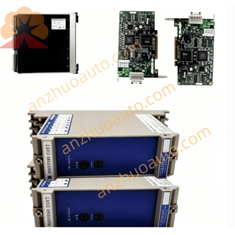
Get a Quote