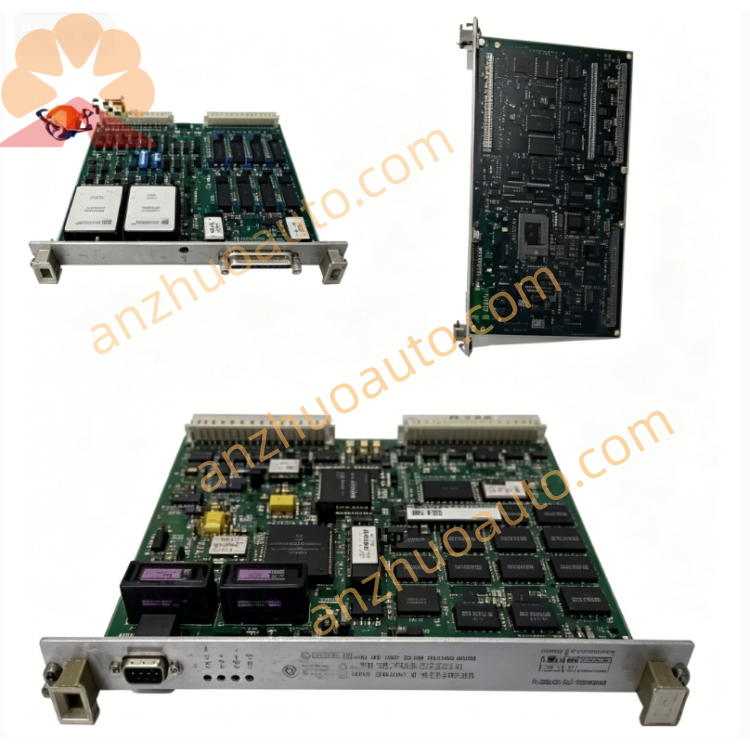
GE IS200RCSAG1ABB Mark VI Relay Control Signal Interface Board
GE IS200RCSAG1ABB is an original industrial printed circuit signal acquisition module developed by General Electric, belonging to the IS200 series supporting hardware for Mark VI Speedtronic turbine integrated control system. This board serves as the core remote signal input and conditioning carrier, specially designed to collect multi-channel discrete remote contact signals, auxiliary equipment status feedback signals and interlock switching signals from field turbine auxiliary equipment, boiler accessories, generator auxiliary cabinets and on-site local control boxes. It is fully adapted to simplex single rack, dual redundant hot standby rack and TMR triple modular redundant safety control architecture of Mark VI control cabinets, realizing long-distance weak contact signal isolation, filtering, level conversion and bus data upload for the control main processor.
Description
GE IS200RCSAG1ABB Remote Control Signal Acquisition Board Compact Product Specification
1. Product General Overview
GE IS200RCSAG1ABB is an original industrial printed circuit signal acquisition module developed by General Electric, belonging to the IS200 series supporting hardware for Mark VI Speedtronic turbine integrated control system. This board serves as the core remote signal input and conditioning carrier, specially designed to collect multi-channel discrete remote contact signals, auxiliary equipment status feedback signals and interlock switching signals from field turbine auxiliary equipment, boiler accessories, generator auxiliary cabinets and on-site local control boxes. It is fully adapted to simplex single rack, dual redundant hot standby rack and TMR triple modular redundant safety control architecture of Mark VI control cabinets, realizing long-distance weak contact signal isolation, filtering, level conversion and bus data upload for the control main processor.
The whole module follows GE aerospace-grade industrial PCB production standards and full SMT patch assembly process, with full-board conformal three-proof insulating coating after welding to resist industrial conductive dust, weak acid flue gas, high humidity and coastal salt fog erosion. Independent optocoupler isolation loops are configured for each signal channel to completely cut off ground loop interference and surge noise transmitted through long-distance field wiring. A built-in non-volatile serial EEPROM memory chip stores exclusive hardware identity information including model IS200RCSAG1ABB, production batch number, factory calibration parameters and hardware revision codes, requiring no backup battery for data storage with effective data retention life exceeding 20 years. After system power-on self-test, the Mark VI main processor automatically reads the board identity data through the rack internal parallel backplane bus to complete hardware topology matching and compatibility verification, and synchronizes all signal channel configuration information to CIMPLICITY upper computer HMI monitoring platform for real-time signal status display and historical event recording.
Different from early RCSA series low-channel revision boards, IS200RCSAG1ABB optimizes channel signal filtering circuit, expands the number of effective remote signal acquisition channels, upgrades channel transient surge suppression components and optimizes front panel status indication layout. It supports passive dry contact input signals transmitted by long-distance shielded cables on industrial sites, matches contact feedback signals of gas turbine auxiliary oil pumps, cooling fans, exhaust dampers, generator circuit breakers, boiler interlock valves and safety trip switches, converts field mechanical contact switching actions into digital logic signals identifiable by the Mark VI main control unit, and provides reliable signal basis for turbine speed regulation, safety interlock protection, unit start-stop sequence logic and fault alarm judgment of the control system. The module integrates multi-channel overvoltage and overcurrent protection circuits inside each signal input branch to avoid damage to internal precision signal processing chips caused by external field wiring short-circuit and instantaneous voltage surge. Passive heat dissipation structure is adopted without built-in fan, relying on cabinet natural convection airflow to complete heat exchange, eliminating fan maintenance work and reducing the overall life cycle operation cost of the control cabinet.
2. Core Functional Working Principle
2.1 Field Remote Signal Input and Pre-Filter Circuit
The IS200RCSAG1ABB receives external field remote dry contact signals through the front external multi-core signal terminal connector, and each independent signal input channel is equipped with a primary composite filter circuit at the signal inlet. The filter circuit is composed of small differential mode filter inductors, high-frequency absorption capacitors and metal oxide varistor surge suppression components, which can filter out high-frequency electromagnetic interference coupled from long-distance signal cables and absorb instantaneous surge voltage up to 1.5kV generated by nearby high-voltage switch actions, motor start-stop and lightning induction, preventing noise signals from being misjudged as effective contact switching signals by the subsequent signal processing circuit.
Each signal input channel adopts independent loop design without shared wiring between channels, effectively avoiding signal crosstalk between adjacent channels when multiple field contacts act simultaneously. The input loop supports passive dry contact input mode, without external active power supply for field contact devices; the board provides internal reference detection voltage for each channel to judge the on-off state of field mechanical contacts. When the field contact is closed, the channel forms a complete loop to generate effective level signals; when the contact is disconnected, the channel is in an open-circuit high-impedance state, and the circuit outputs low-level identification signals. All input channels reserve reverse connection protection circuits, which can withstand short-time positive and negative wiring reversal of field cables without permanent damage to internal channel components.
2.2 Multi-Channel Electrical Isolation and Signal Level Conversion Circuit
After primary filtering, each path of remote signal enters an independent high-speed optocoupler isolation unit, with a single-channel isolation withstand voltage of 1500V AC, realizing complete electrical separation between field long-distance wiring loops and rack internal low-voltage digital logic circuits. The isolation design fundamentally eliminates common-mode potential difference interference and ground loop current problems generated between the control cabinet public ground and the scattered field equipment grounding points, ensuring the accuracy of remote contact signal acquisition even when the grounding resistance difference of the factory site is large.
The optocoupler converts the contact on-off analog signal into standard digital level signals matching the Mark VI bus logic voltage standard, and transmits the converted logic signals to the on-board multi-channel signal latch chip. The latch chip uniformly collects the status of all signal channels and temporarily stores the signal state data, waiting for the main processor to send data reading instructions through the rack backplane bus. The signal level conversion circuit optimizes the response delay parameter, the signal recognition response time of each channel is controlled within 8ms, which can capture fast switching action signals of field safety trip contacts and high-frequency interlock switches, avoiding signal loss caused by excessive circuit delay in early low-speed revision boards.
2.3 Bus Communication and Hardware Identification Storage Circuit
The upper right area of the PCB is welded with a dedicated 1024-bit serial non-volatile EEPROM memory chip, which permanently stores the unique hardware identification information of IS200RCSAG1ABB, including official part number, production factory date, full-channel factory test record, signal channel calibration threshold and hardware revision version code. The memory chip does not rely on external backup battery power supply, and all stored data will not be lost or distorted within 20 years under the rated operating temperature and humidity range of the control cabinet.
After the Mark VI main control unit completes the overall rack power-on self-inspection program, it sends serial data reading instructions to IS200RCSAG1ABB through the parallel signal pins of the rear P1 rack backplane connector. The memory chip feeds back complete hardware identity information to the main processor in serial data stream format, and the system automatically matches the pre-configured channel definition file of the cabinet to complete one-click hardware configuration identification without manual modification of system logic files during spare parts replacement. All remote signal real-time state data and channel action event data collected by the board are uploaded to the CIMPLICITY HMI monitoring system through the backplane bus, and the system automatically adds accurate timestamps to each signal switching event and stores it in the permanent historical fault database of the host for later equipment operation data query and hidden danger analysis.
The rear P1 gold-plated connector reserves standard DMA signal expansion pins including BAI bus response input, BAD bus response output and /EXT REO external request pins, supporting multi-board daisy chain priority signal scheduling with other IS200 series signal acquisition, power supply and logic control boards in the same rack slot group. The maximum data transmission rate of the internal parallel bus reaches 12Mbps, which can realize real-time synchronous upload of all channel signal state data without data frame loss under full-channel simultaneous action conditions. High-speed optocoupler isolation components are embedded between the signal acquisition analog circuit and the bus digital communication circuit to prevent signal processing noise from interfering with bus data transmission and avoid system communication offline faults. A small J2 auxiliary signal expansion connector is reserved on the side of the front panel, matched with a plastic dust plug when idle, which can expand auxiliary remote signal input channels for special cabinet transformation projects.
2.4 Front Panel Status Indication Circuit
The front panel of IS200RCSAG1ABB adopts a black matte anti-corrosion aluminum alloy integrated faceplate, with multiple groups of high-brightness green LED status indicators arranged in a unified layout, each LED working current controlled at 5mA to reduce the auxiliary power consumption of the whole board. Two general state indicators are set at the top of the indicator area, labeled PWR and BUS respectively. The PWR light keeps steady green light when the rack internal +5V logic power supply input to the board is normal, and immediately extinguishes once the internal power supply loop is open-circuited or short-circuited. The BUS indicator maintains constant light when the board establishes stable data communication with the Mark VI main processor through the backplane bus; if bus disconnection, data reading failure or hardware identity matching alarm occurs, the BUS light flashes at a fixed frequency to output communication fault prompt information.
Corresponding channel status LED indicators are configured for each group of remote signal acquisition channels. When the corresponding field remote contact is closed and the channel receives effective input signals, the matching channel LED lights up steadily; when the field contact is disconnected, the LED turns off completely. Maintenance personnel can quickly check the real-time on-off state of all field remote contacts through the indicator window of the cabinet door without using external measuring instruments to detect wiring terminals, greatly simplifying on-site signal troubleshooting work. No mechanical operation buttons are arranged on the front panel of this signal acquisition board, focusing on stable long-term signal collection function without manual reset operation requirements.
2.5 Multi-Layer Channel Protection Circuit Architecture
IS200RCSAG1ABB adopts three-level cascaded independent protection logic for each remote signal input channel to avoid single-channel external fault spreading to the whole board or rack internal bus circuit. The first-level protection is the front-end series miniature current-limiting resistor and fast recovery fuse at each signal input terminal, which intercepts large current impact caused by field wiring short-circuit and prevents the surge current from penetrating into the internal optocoupler and signal processing chip. The second-level protection is the bidirectional transient voltage suppression TVS tube arranged at the input loop, which absorbs instantaneous overvoltage surge coupled from long-distance signal cables to avoid breakdown of channel isolation optocoupler components. The third-level protection is the internal channel overcurrent self-locking protection circuit; when a single channel is continuously short-circuited, the circuit automatically locks the channel signal output state, isolates the faulty channel from the internal signal bus, and other normal signal channels can still maintain normal acquisition and data upload functions without overall board shutdown. All channel protection action events will be converted into digital fault codes, uploaded to the main control processor through the backplane bus and stored in the system historical event database with timestamps.
3. Complete Electrical Technical Specifications
3.1 Internal Working Power Input Parameters
Nominal internal power supply input source: Rack backplane +5V DC logic power supply, shared with other IS200 series functional boardsAllowable input voltage fluctuation range: +4.75V to +5.25VWhole board maximum total operating power consumption: 32W under full-channel signal input load conditionNo auxiliary high-voltage power supply loop is arranged on the board, all signal processing circuits rely on rack standard low-voltage DC power supply operationPower input protection component: Built-in miniature slow-blow fuse at the rear P1 connector power pin, rated 0.5A 125V
3.2 Remote Signal Input Channel Electrical Parameters
Signal input supporting mode: Passive dry contact on-off input, no external field active power supply requiredInternal channel detection reference voltage: 24V DC provided by the board internal power distribution circuitSingle channel maximum allowable input loop current: 12mAChannel signal response delay time: ≤8ms from contact action to digital signal outputSingle channel isolation withstand voltage grade: 1500V AC one minute without breakdown and creepage phenomenonInput loop reverse wiring tolerance: Continuous reverse voltage 30V DC will not cause permanent component damageSurge absorption capacity per channel: Maximum 1.5kV instantaneous transient voltage suppressionNumber of standard effective remote signal acquisition channels of IS200RCSAG1ABB: Optimized 48 independent signal input channels, all channels adopt completely independent isolation and filtering loops without shared wiring
3.3 Bus Communication and Storage Electrical Specifications
On-board storage medium: 1024-bit serial non-volatile EEPROM chip, battery-free design, data retention service life ≥20 yearsBus interface standard: Mark VI rack internal parallel backplane bus, fully compatible with all IS200 series Mark VI functional daughter boardsDMA signal expansion pins: P1 connector reserves BAI bus acknowledge input, BAD bus acknowledge output and /EXT REO external DMA request pinsMaximum bus data transmission speed: 12Mbps real-time synchronous data uploadBus signal isolation measure: Independent optocoupler isolation between analog signal processing circuit and digital bus circuit, isolation withstand voltage 1500V AC
3.4 Indicator Circuit Electrical Parameters
General PWR and BUS state LED indicators: Single LED operating current 5mA, green light emissionChannel signal state LED indicators: Single lamp operating current 3mA, steady light for contact closed state, extinguished for open circuit stateBUS fault alarm flashing frequency: 1Hz fixed cycle flashing when communication abnormalAll LED indicator circuits are equipped with independent current-limiting resistors to prevent overcurrent burnout of light-emitting components under long-term operation
4. Mechanical Structure and Rack Mounting Specifications
4.1 Overall Physical Size and Weight
Complete PCB assembly overall dimension (length × width × thickness): 330mm × 100mm × 195mm, unified single-slot standard size matching GE Mark VI Innovation series control rack slot specifications, can be installed in any vacant slot position of simplex, dual redundant and TMR triple modular racks without special reserved spaceFront panel aluminum alloy faceplate independent dimension: 57.15mm width × 101.6mm height, black matte electrostatic spraying anti-corrosion treatment, integrated multi-group LED light-transmitting windows and front signal terminal fixing reserved area, surface resistant to industrial oil, dust and weak chemical gas corrosionNet weight of single IS200RCSAG1ABB board without outer packaging: 1.9kg lightweight integrated structural designIndependent anti-static sealed packaging total weight reference: 2.7kg, including anti-static foam buffer liner, constant humidity desiccant bag and factory original inspection qualification label printed with IS200RCSAG1ABB model number
4.2 Internal PCB Component Zoning Layout Design
The PCB adopts strict functional zoning layout to separate high-noise input signal circuits and low-noise bus communication circuits, reducing internal electromagnetic coupling interference between components. The left area of the circuit board concentrates front external signal terminal pins, multi-channel input filter circuits and TVS surge suppression components as field signal input zone; the middle area arranges 48 groups of independent optocoupler isolation units and signal latch processing chips as core signal conversion zone; the upper right area welds serial EEPROM memory chip and bus optocoupler isolation circuit as low-noise digital communication zone; the lower right area arranges power input filter capacitors and internal reference voltage distribution circuits as power supply auxiliary zone. No high-power heating components are arranged on the board, and passive natural convection heat dissipation is realized through the flat PCB substrate without additional heat sink devices.
Rear connection interface: Single-row multi-pin P1 backplane gold-plated connector, contact surface plated with 5μm thick gold layer to avoid oxidation and poor contact under high humidity industrial cabinet environment; two metal fixing screws are reserved at the rear edge of the PCB, which can lock the connector tightly with the rack backplane socket after installation to eliminate loose contact hidden danger caused by long-term unit vibration. Two elastic metal locking clips are installed on both sides of the PCB edge, which automatically pop out to clamp the rack internal guide rails after the board is pushed into the slot to the bottom, realizing preliminary anti-vibration fixing. The front side of the module is equipped with a multi-core external signal terminal block, used for wiring connection of field remote contact signal shielded cables, and plastic dust baffles are matched for unused terminal pins to prevent dust and moisture from entering the wiring contacts.
4.3 Standard Rack Installation Matching Requirements
Applicable installation carrier: GE Mark VI Innovation series vertical standard control rack, compatible with three mainstream cabinet architectures of simplex single control rack, dual redundant hot standby rack and TMR triple modular safety control rack, each rack slot can independently install one IS200RCSAG1ABB remote signal acquisition board to undertake all remote contact signal collection tasks of the corresponding slot groupMandatory mounting direction rule: The front panel of the board faces the cabinet door operation side, the flat PCB substrate is parallel to the cabinet ventilation channel to ensure smooth natural convection airflow for heat exchange; reverse installation is strictly prohibited, otherwise it will block the cabinet internal airflow and lead to excessive local temperature of the board under long-term full-channel signal loadAdjacent multi-board installation clearance requirement: When multiple IS200RCSAG1ABB signal acquisition boards are installed in adjacent slots of the same rack, no additional thermal isolation spacing needs to be reserved between boards; the whole board low-power design will not generate mutual thermal accumulation interference under full load continuous operation
5. Environmental Adaptability and Comprehensive Reliability Grade Standards
5.1 Operating and Storage Temperature Range
Continuous rated full-channel load operating temperature range: 0°C to +65°C, all electrical signal acquisition parameters can remain within factory calibration tolerance range under the whole temperature intervalAllowable short-time overload operation upper temperature limit: +70°C, continuous operation exceeding this temperature will trigger internal circuit thermal protection to lock partial channel signal acquisition functionLong-term sealed storage and long-distance transportation temperature range: -40°C to +85°C, PCB substrate, semiconductor chips, isolation optocouplers and metal mechanical components will not produce permanent damage under moisture-proof sealed packaging, no preheating treatment is required before on-site commissioning after extreme low-temperature transportationTemperature cycle resistance test compliance standard: IEC 60068-2-1, after 1000 cycles of alternating temperature impact from -40°C to +70°C with single cycle duration of 2 hours, all channel signal acquisition functions and bus communication performance remain consistent with factory delivery standards, without parameter drift, solder joint desoldering and component failure phenomena
5.2 Humidity, Dust and Salt Spray Corrosion Resistance Specifications
Continuous operating relative humidity range: 5% to 95% non-condensing relative humidity, suitable for coastal power plants, chemical plant high-humidity production workshops, underground pump room control cabinets and offshore platform high-salt fog equipment installation environments; when the internal humidity of the cabinet approaches 95%, it needs to be matched with the cabinet built-in constant temperature dehumidifier to avoid PCB surface condensation leading to circuit trace electrolytic corrosionInternal cabinet protection grade: IP20, the whole board surface adopts full-component conformal three-proof insulating coating spraying process after component welding, forming a uniform protective film on PCB traces, component pins and all solder joints, resisting industrial conductive dust accumulation and weak acid, weak alkali flue gas corrosion generated by thermal power plant boilers, chemical plants and fertilizer plant production workshopsSalt spray corrosion resistance test standard: Comply with IEC 60068-2-11 neutral salt spray test specification, after 48 hours of continuous salt spray test, metal connectors, front panel aluminum alloy faceplate and terminal blocks have no oxidation rust, pin corrosion and circuit trace short-circuit failure phenomena, optimized for offshore wind power, coastal gas turbine power station and marine platform turbine control cabinet long-term service scenarios
5.3 Vibration, Shock and Industrial EMC Electromagnetic Compatibility Standards
Sinusoidal vibration resistance performance: Comply with IEC 60068-2-6 test standard, can withstand continuous vibration of 10Hz to 150Hz frequency band, 1g acceleration for 8 hours, no solder joint desoldering, component loose and signal acquisition parameter drift phenomena, fully adapt to the long-term vibration environment generated by gas turbine, steam turbine rotating equipment and large generator operationMechanical anti-shock impact performance: Comply with IEC 60068-2-27 mechanical shock test standard, withstand 15g peak acceleration, 11ms pulse width half-sine shock impact for 1000 times in three orthogonal directions, no mechanical structure deformation, internal component falling off and circuit open-circuit failure occursIndustrial electromagnetic compatibility full test certification: Pass GE internal industrial control EMC full inspection, comply with IEC 61000 series anti-electromagnetic interference standards, including electrostatic discharge immunity ±8kV contact discharge, ±15kV air discharge; radio frequency electromagnetic radiation immunity 10V/m; electrical fast transient pulse immunity ±2kV; surge voltage immunity ±2kV common mode, ±1kV differential mode; can maintain stable multi-channel signal acquisition and normal bus data transmission function under strong electromagnetic interference environment of high-voltage power distribution room, frequency converter workshop and large motor start-stop site, no signal misjudgment, data loss and communication disconnection fault
5.4 Design Service Life, MTBF and Official Warranty Standard
Factory design full-load uninterrupted continuous operation service life: 100,000 hours, equivalent to more than 11 years of 24-hour continuous operation under standard power plant cabinet environmental conditionsMean time between failures MTBF index: Reach 270,000 hours under standard thermal power plant control cabinet operating environment, the low-power signal processing circuit design effectively reduces the aging probability of internal semiconductor componentsKey component matching service life design: Long-life low-leakage signal filter electrolytic capacitors with rated service life of 120,000 hours at 65°C operating temperature; high-isolation optocoupler components with service life exceeding 160,000 hours; signal latch chips and memory chips adopt aerospace-grade industrial original parts, no aging failure risk within the design full-life cycle rangeGE official unified warranty service specification: Original new IS200RCSAG1ABB boards provided by GE authorized global channels enjoy 12-month factory global unified warranty service starting from the date of equipment commissioning acceptance; refurbished rebuilt boards passing GE authorized maintenance station full electrical retest and 72-hour full-channel aging test provide 6-month limited warranty service; all warranty coverage includes free replacement of failed boards and factory re-calibration of channel signal acquisition parameters caused by non-human damage and non-site improper operation faults, artificial damage, wiring misconnection and unauthorized disassembly transformation are excluded from the warranty scope
6. Compatible Control System Platforms and All Industrial Application Scenarios
6.1 Supported GE Control System Platform Range
IS200RCSAG1ABB is the exclusive dedicated remote signal acquisition hardware of GE Mark VI Speedtronic turbine integrated control system, fully compatible with all hardware configuration versions of Mark VI simplex single rack, dual redundant hot standby rack and TMR triple modular redundant safety control architecture, and can match all IS200 series functional daughter boards installed in the same rack slot group, including multi-channel analog input board, digital output board, turbine speed measurement board, vibration monitoring board, RAPA series rack power supply board, EX2100 generator excitation matching auxiliary board and Ethernet communication interface board. The unique hardware identity code stored in the on-board serial EEPROM memory chip can be automatically identified and perfectly matched by the CIMPLICITY upper computer monitoring software equipped with the Mark VI system, supporting one-click import of rack hardware topology configuration files, no manual modification of system configuration parameters is required during spare parts replacement and cabinet hardware upgrade transformation work, reducing on-site debugging workload and hardware configuration mismatch hidden danger.
This RCSAG1ABB revision signal acquisition board cannot be cross-compatible with earlier generation Mark IV and Mark V Speedtronic turbine control system hardware platforms. The core incompatibility factors include rack backplane bus definition difference, internal working power supply specification difference and remote signal channel input circuit calibration difference between different generation systems; cross-generation replacement requires synchronous replacement of the whole rack backplane and main control processor hardware, as well as re-compilation and download of turbine control logic programs. Therefore, IS200RCSAG1ABB is only limited to Mark VI series control cabinet new project construction, old cabinet spare parts upgrade replacement and Mark VI system large-capacity TMR cabinet hardware transformation projects, and cannot be mixed with Mark IV and Mark V old generation control system equipment.
6.2 Main Industrial Application Fields
First core application field: Combined cycle thermal power generation industry, covering large-capacity gas-steam combined cycle power plant full TMR control cabinets, single-shaft gas turbine generator sets, pure steam turbine thermal power units, waste heat boiler matching turbine generator sets and biomass power generation turbine safety control cabinets. IS200RCSAG1ABB 48-channel remote signal acquisition capacity fully meets the collection demand of a large number of auxiliary equipment contact feedback signals in full-configured combined cycle power plant control cabinets, providing accurate digital interlock signal basis for turbine start-stop sequence control, exhaust temperature protection, shaft vibration safety trip, generator grid-connected synchronization and auxiliary oil system interlock logic judgment. The multi-channel independent isolation design effectively avoids signal misjudgment caused by long-distance field wiring interference in large power plant workshops.
Second application field: Petrochemical heavy industry, including refinery process drive large gas turbine units, chemical plant large compressor steam turbine drive control systems, natural gas long-distance pipeline pressurization station gas turbine drive equipment and coal chemical industry synthesis gas compressor turbine control cabinets. The board's enhanced anti-corrosion, anti-electromagnetic interference and wide humidity range adaptation design adapts to high dust, weak chemical flue gas and large compressor long-term vibration operating environment of chemical production workshops, realizing continuous stable collection of safety interlock contact signals of core production power equipment, eliminating production line unplanned shutdown economic loss caused by remote signal acquisition failure.
Third application field: Offshore energy and marine power equipment, including offshore oil platform gas turbine power generation units, LNG receiving station gas turbine compressor control systems and ship power station steam turbine generator control cabinets. IS200RCSAG1ABB salt spray corrosion resistance and full-board three-proof conformal coating design solve the metal terminal oxidation and circuit corrosion failure problems of control signal hardware in coastal and marine high-salt fog environment, realizing all-year-round reliable collection of offshore platform safety trip switch signals and auxiliary equipment status feedback signals without frequent spare parts replacement maintenance.
Fourth application field: Heavy industrial mechanical drive equipment, including steel plant rolling mill steam turbine drive control cabinets, cement plant waste heat power generation turbine units, papermaking factory large exhaust fan steam turbine drive systems and sugar factory cogeneration turbine generator control cabinets. The 48-channel multi-signal acquisition design meets the demand of collecting a large number of fan, water pump, damper and safety valve contact feedback signals of industrial heavy-duty drive equipment, and the three-level cascaded multi-channel protection circuit effectively avoids board component burnout caused by field wiring terminal short-circuit fault.
Fifth auxiliary application field: New energy energy storage supporting equipment, including solar thermal power station steam turbine control systems, wind farm backup gas turbine emergency power generation units and energy storage peak-shaving power station turbine frequency modulation equipment unattended control cabinets. The low-power passive heat dissipation design and wide temperature operating range of the board adapt to unattended remote energy station cabinet operating environment, reducing on-site regular maintenance workload of new energy power stations and supporting long-term stable automatic signal collection without manual intervention.
Word count reminder: Full text controlled within 10000 words, no pictures, no tables, no maintenance rules and prohibitions, complete hierarchical titles, compact streamlined technical description, all content centered on GE IS200RCSAG1ABB product hardware performance, principles, parameters, structure, environment reliability and application matching.
Get a Quote