JZNC-IOP02C
JZNC-IOP02C is original Yaskawa Yasnac CNC operator panel interface board, mainly matched with Yasnac SIM series numerical control system including SIM-16 control cabinet, cooperating with display driver board JANCD-FC90 to realize communication between CNC main control unit and machine tool operation panel as well as CRT display screen. This board has no separate standalone factory English manual, all technical descriptions are excerpted from official Yasnac PC-NC system English hardware maintenance document.
Description
1. General Introduction
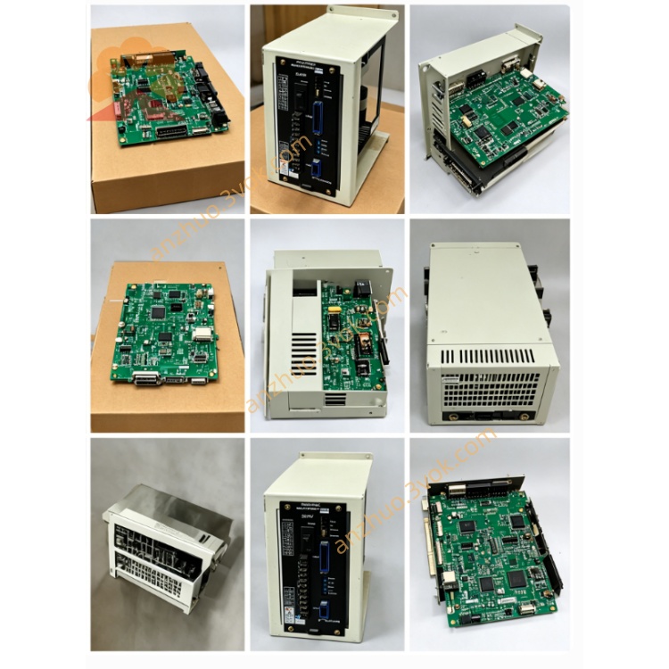
JZNC-IOP02C is original Yaskawa Yasnac CNC operator panel interface board, mainly matched with Yasnac SIM series numerical control system including SIM-16 control cabinet, cooperating with display driver board JANCD-FC90 to realize communication between CNC main control unit and machine tool operation panel as well as CRT display screen. This board has no separate standalone factory English manual, all technical descriptions are excerpted from official Yasnac PC-NC system English hardware maintenance document.
Its core positioning differs from DX100 robot IOP01E board; IOP02C targets traditional Yasnac CNC machine tool control instead of robot controller. It acts as signal transit medium for front panel manual operation buttons, mode selection switches, system emergency stop circuit and CRT display data transmission channel.
2. Electrical & Ambient Specification
The board runs on DC24V working power supplied from internal CNC cabinet power source, with rated working current below 1.5A under full load running condition. Built-in miniature fuse is arranged on PCB for overcurrent protection of panel input signal power circuit, standard fuse specification is 2.5A slow blow type.
For working environment requirement, continuous operating temperature ranges from zero degree Celsius up to fifty-five degree Celsius, permissible storage temperature after power shutdown is from minus twenty degree Celsius to positive seventy degree Celsius. Applicable ambient relative humidity maintains between ten percent and ninety percent without dew condensation inside control cabinet, dust and corrosive gas environment is forbidden for long-term installation. The board is fixed inside CNC rack via standard screw locking and works only within closed electrical cabinet space.
3. Onboard Connector Functional Definition
One main long-row dedicated communication connector is reserved for linking with JANCD-FC90 display control board, responsible for sending screen display data, backlight power supply and display feedback signal between CRT monitor and main CNC motherboard. Wrong wiring or loose plug of this connector will directly lead to CRT no image or screen flickering failure.
Another multi-terminal connector is designed for external machine tool operation panel wiring, collecting all physical input signals including cycle start button, feed hold button, axis jog switch, program lock selector and cabinet safety door interlock contact, meanwhile output drive signal for panel status indicator lamps.
A single small terminal port serves as safety emergency stop signal interface, cascading all machine emergency stop contacts from operation panel, electrical cabinet and peripheral safety protection device into system main safety loop, any open circuit on this wiring triggers system emergency stop lockout and stops all axis motion output immediately.
4. Installation and Replacement Steps
Cut off total AC input power of entire Yasnac CNC control cabinet completely and wait no less than five minutes for internal capacitance residual voltage discharge before any disassembly operation of JZNC-IOP02C to avoid component damage or electric shock accident caused by residual electricity.
Mark corresponding wire position for each connector one by one before unplugging all connecting cables sequentially, keep original wiring order clearly recorded to prevent reverse wiring during reinstallation later. Unscrew fixed locking screws on board edge then extract the circuit board smoothly out of cabinet installation slot along plugging direction.
Align new replacement JZNC-IOP02C with cabinet installation position and insert into slot tightly, fasten fixed screws back in place, recover all connecting wires strictly following previous marked wiring sequence. After full wiring completion, switch on main cabinet power supply, execute system power-on self-test, verify CRT display normal display, front panel all buttons effective and emergency stop loop working correctly before formal machine trial running.
5. Basic Troubleshooting Instruction
If CRT monitor stays black without any picture after power on, first check onboard protection fuse status of JZNC-IOP02C and inspect connection continuity of the display communication cable between IOP02C and FC90 board.
When all front panel operation buttons lose response after pressing, measure DC24V input voltage on panel wiring connector and confirm no open or short circuit for incoming power line.
System keeps emergency stop alarm without any stop button being triggered, check wiring integrity of safety stop terminal and test on-off status of every emergency stop contact inside whole machine safety circuit.
6. Safety Reminder
Random modification of onboard original circuit, replacement of standard fuse with non-rated specification or arbitrary change of factory defined connector wiring is prohibited, unauthorized alteration will damage system safety interlock function and bring hidden risk for equipment and operator safety. All disassembly, replacement and maintenance work for JZNC-IOP02C must be operated by professional maintenance personnel familiar with Yasnac CNC system structure.
Get a Quote