JZNC-GOP07
Description
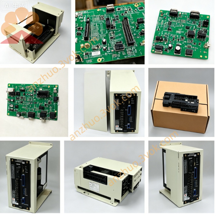
1. Product Overview
2. Core Functional Description
2.1 Display & Program Management
Built-in 7-inch monochrome industrial LCD with adjustable backlight; real-time display actual axis coordinate, spindle RPM, feed rate, machining NC program, system alarm codes and digital I/O monitoring status.
Support multi-character input: English numeric & alphabet, Japanese; complete NC program create, edit, copy, delete, block skip and single-block setup via front function keys.
2.2 Machine Running Control Functions
Mode Selection Rotary Switch: 4 standard operation modes: JOG(Manual Jog), MDI(Manual Data Input), AUTO(Auto Run), ZRN(Origin Return); safety interlock design prevents mode switching during automatic machining running.
MPG Manual Pulse Generator: Feedrate override knob, spindle speed adjustment potentiometer + incremental handwheel for X/Y/Z/4th axis fine incremental positioning.
Axis Jog Buttons: Independent +/- direction jog keys for X, Y, Z and optional 4th/5th auxiliary axes plus rapid traverse shortcut button.
Process Control Keys: CYCLE START, FEED HOLD, SYSTEM RESET, SINGLE BLOCK, OPTIONAL STOP, spindle CW/CCW/STOP, coolant ON/OFF, manual tool change trigger keys.
2.3 Safety Circuit Module
3. Electrical Specifications
Rated Input Power: DC24V ±10% (supplied from CNC cabinet internal control power source)
Working Current: Rated ≤720mA; total power consumption: 14~17W
Communication Interface: Rear dedicated multi-core plug connector for bus communication + DC24V power input to JZNC main control rack; differential signal transmission for handwheel MPG to resist workshop inverter interference
Internal protection: Built-in anti-surge fuse on main power input circuit
4. Environmental Working Parameters
Continuous operating ambient temperature: 0℃ ~ +55℃ (inside sealed CNC cabinet)
Storage temperature range: -25℃ ~ +70℃
Relative humidity: 25%~80%RH, no condensation allowed
Protection Grade: Front operation panel IP53 (anti-dust, splash-proof for cutting fluid); rear wiring cavity IP20
Max applicable altitude: ≤1000m without power derating; avoid installation in corrosive gas, metal dust & heavy oil mist environment
5. Rear Connector & LED Indicator Definition
5.1 Rear Wiring Connector
5.2 Onboard Status LED
PWR(Green): Constant ON = DC24V input normal; OFF = power loss or internal fuse blown
COM(Green): Flashing = normal data communication with main CPU board; steady OFF = communication failure or loose connector
ALM(Red): Constant ON = emergency stop triggered or internal panel hardware fault; intermittent flicker = temporary signal interference or peripheral interlock fault
6. Installation & Replacement Operation Steps
Cut off total cabinet AC power supply, wait ≥15min for internal high-voltage capacitor full discharge to avoid electric shock damage.
Remove cabinet front panel fixed screws, unplug rear dedicated bus connector, extract faulty GOP07 unit outwards.
Clean connector pin oxidation with anhydrous alcohol, align new JZNC-GOP07 rear plug with cable socket and fully lock connection.
Fix panel mounting screws, restore cabinet power, power on CNC system; test LCD backlight, all function keys, handwheel signal and emergency stop function before trial operation.
7. Common Fault Troubleshooting
Entire screen black + PWR lamp off: Inspect cabinet DC24V output voltage and internal panel protection fuse; replace fuse with same specification when blown.
Display normal but all jog keys invalid: Check loose rear connector or oxidized pins, clean contact terminals.
Handwheel no pulse response: Test handwheel differential wiring open/short; replace GOP07 if peripheral wiring intact.
ALM lamp always lit: First confirm emergency stop fully reset; check machine door interlock safety circuit if E-stop is released.
8. Compatible Matching System & Equipment
Matching CNC System: YASKAWA i80, i82 series YASNAC controller
Applicable Machine: Mori Seiki original vertical machining center, CNC lathe, tapping center
Matching spare parts: JZNC series main CPU board, JANCD series I/O expansion PCB
Get a Quote