JANCV-MCP01
JANCV-MCP01 is an original Yaskawa Motoman main CPU control board exclusively developed for MRC series robot controllers. It is a revised derivative model based on JANCU-MCP01, acting as the core arithmetic and processing center of the whole robot control system. Designed with plug-in gold finger structure for installation on cabinet internal backplane slots, it cooperates with MSV series servo control boards, I/O expansion boards and communication boards to build a complete robot control system. This board is mainly matched with early MRC industrial robots widely applied in automotive spot welding, arc welding, material handling and component assembly automatic production lines, and serves as essential replacement spare part for maintenance of aged MRC control cabinets. All products pass industrial aging test and EMC anti-interference inspection to support long-time continuous startup and shutdown under workshop working conditions and comply with CE industrial safety certification standards.
Description
1. Product Brief Introduction
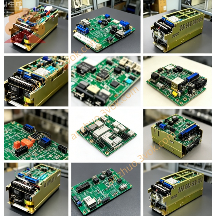
JANCV-MCP01 is an original Yaskawa Motoman main CPU control board exclusively developed for MRC series robot controllers. It is a revised derivative model based on JANCU-MCP01, acting as the core arithmetic and processing center of the whole robot control system. Designed with plug-in gold finger structure for installation on cabinet internal backplane slots, it cooperates with MSV series servo control boards, I/O expansion boards and communication boards to build a complete robot control system. This board is mainly matched with early MRC industrial robots widely applied in automotive spot welding, arc welding, material handling and component assembly automatic production lines, and serves as essential replacement spare part for maintenance of aged MRC control cabinets. All products pass industrial aging test and EMC anti-interference inspection to support long-time continuous startup and shutdown under workshop working conditions and comply with CE industrial safety certification standards.
2. Detailed Functional and Parameter Description
2.1 Core Control Functions
The onboard master control chip takes full charge of robot trajectory interpolation calculation, teaching program analysis, full-axis servo closed-loop operation and peripheral interlock logic processing, supporting maximum 21-axis coordinated motion as well as synchronous dual-robot operation and follow-up control of external auxiliary servo axes. Built-in flash memory stores robot origin parameters, servo calibration data, workpiece positioning coordinates and user-defined operation programs with sufficient storage space to accommodate massive position data for complex multi-process automatic workstation programming requirements. Equipped with integrated onboard fault diagnosis function, it collects abnormal signals such as servo overcurrent, encoder disconnection, communication breakdown and safety circuit cut-off in real time, converts fault information into corresponding alarm codes and transmits codes to handheld teach pendant for quick on-site troubleshooting. Multiple built-in industrial communication circuits realize data exchange with servo boards, teach pendants and upper PLC systems; users can modify programs online via teach pendant or upload/download offline programs from external computer through dedicated debug port. Meanwhile, it independently processes all cabinet digital input and output signals to manage interlock of safety door switches, fixture clamping signals and conveyor start-stop commands to achieve automatic linkage operation of the whole workstation.
2.2 Electrical Specifications
Power is supplied from DC24V ±10% bus of cabinet backplane, rated operating current is less than 500mA with total power consumption around 7 watts. Isolated power design is adopted for core control circuit to avoid component damage caused by instantaneous surge fluctuation of industrial power grid. An independent overcurrent protection fuse is arranged on PCB to cut off board power supply automatically when external wiring short-circuit occurs so as to prevent PCB burnout. External communication ports include RS232 debug serial port and RS485 bus terminals compatible with mainstream Modbus RTU and DeviceNet fieldbus protocols for connection of peripheral PLC and upper monitoring equipment; surge protection circuits are added on all signal terminals to improve stability under severe electromagnetic interference from welding machines and inverters in welding workshops.
2.3 Ambient Operating Conditions
Continuous working temperature ranges from 0°C to +55°C while storage temperature for spare parts covers -25°C to +70°C. Applicable relative humidity stays between 30% and 80%RH under non-condensing environment. Installation in areas with corrosive gas, conductive dust, welding spatter or strong high-frequency electromagnetic radiation is strictly forbidden. With IP20 protection grade, the board can only be installed inside sealed control cabinets instead of open damp outdoor locations. It can work normally below altitude of 1000 meters without power derating and applies passive natural convection cooling without built-in cooling fans.
2.4 On-board Connector Definition
Gold finger connector at the bottom inserts into designated backplane slot to receive DC24V input and realize high-speed internal bus communication with other functional boards without extra external power wiring. Three types of external interfaces are arranged on front panel including dedicated teach pendant communication port, PC program debug serial port and field bus wiring terminal. Hidden reserved pins are exclusively for factory calibration debugging and shall remain vacant during regular equipment operation.
2.5 LED Indicator Explanation
Constant lit green PWR LED means normal DC24V power input from backplane; lamp off indicates slot power failure or blown onboard protection fuse. Periodically blinking green RUN LED proves normal cyclic execution of CPU system program; permanent off stands for corrupted system program or serious hardware damage. Intermittent flashing yellow COM LED represents stable data exchange with teach pendant and external devices; continuous off is caused by broken communication cable or mismatched bus parameters. Steady red ERR LED lights up under severe faults including lost system parameters, disconnected servo bus and internal hardware failure; short intermittent flash usually results from accidental trigger of external safety signals or temporary electromagnetic interference.
2.6 Installation and Commissioning Procedures
Cut off total AC power supply of control cabinet before any disassembly or replacement work and wait at least 15 minutes for full discharge of internal high voltage capacitors to avoid component breakdown by residual voltage. Align PCB gold finger with corresponding backplane slot and insert smoothly until locking buckle is secured, then fasten all external communication cables on front panel to eliminate poor contact. After hardware installation and power restoration, MRC controller automatically recognizes JANCV-MCP01 hardware. When replacing with blank new board, import original backup robot parameters and user programs via teach pendant or external PC, then complete origin calibration of all servo axes before trial production operation.
2.7 Common Troubleshooting Guide
If PWR indicator keeps off, first measure DC24V output of corresponding backplane slot and check integrity of onboard fuse; replace fuse with same specification and reinsert board to fix poor gold finger contact. When RUN lamp is off with normal power supply, clean gold finger with anhydrous alcohol to remove dust and re-install board; replace entire board if fault remains which implies internal circuit damage. Continuous ERR lighting needs inspection of peripheral wiring including encoder cables and safety circuits; replace control board if no external abnormal condition is found. No blinking COM LED with failed teach pendant connection requires cable integrity check and parameter reset after rewiring.
2.8 Regular Maintenance Instructions
All maintenance and cable plugging operations must be performed under fully powered-off cabinet status. Conduct routine maintenance every six months, wipe accumulated dust on PCB with dry lint-free cloth and inspect aging or loose external connecting cables. Complete board replacement is the official recommended solution once hardware damage is confirmed; arbitrary disassembly of discrete onboard components for partial repair is prohibited. Keep inside cabinet dry and clean during long-term operation to prevent PCB copper layer corrosion and short-circuit faults caused by dampness.
Get a Quote