
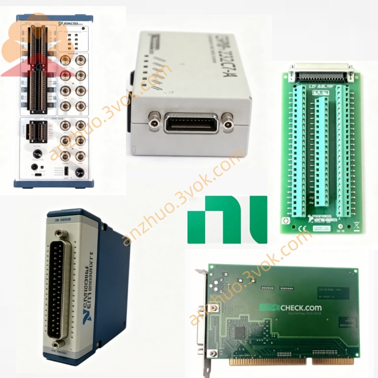
NI PXIe-2725 18CH 8Bit Programmable Resistor Module
The PXIe‑2725 (part number 781986‑25) is an 18‑channel, 8‑bit programmable resistor module for PXI Express, designed to simulate resistive devices such as potentiometers, RTDs, voltage dividers, and bridge circuits. It uses reed relays to set resistance in 1 Ω steps from 1 Ω to 255 Ω per channel, making it ideal for hardware‑in‑the‑loop (HIL) validation, sensor simulation, and precision resistive load testing in automotive, aerospace, and industrial systems.
Description
Model Nomenclature
PXIe represents the PXI Express high-speed modular instrument bus. The number 27 stands for the series of programmable resistor and simulation modules. 2725 refers to an 18-channel programmable resistor module featuring 8-bit resolution, 1 ohm step size and a resistance range of 1 ohm to 255 ohms.
Technical Specifications
The module uses a standard 3U single-slot form factor and can be installed in PXIe hybrid or peripheral slots. It has 18 independent resistance channels. The resistance resolution is 1 ohm, and the adjustable range per channel is 1 ohm to 255 ohms. At 23 degrees Celsius, the resistance accuracy is less than 5.0% for the range of 20 ohms to 64 ohms, and less than 2.0% for the range of 64 ohms to 255 ohms. It is equipped with gold-plated contact reed relays. The maximum allowable voltage is 60 VDC or 30 VAC RMS, and the maximum current per channel is 300 mA. The maximum power dissipation of a single channel under resistive load is 5 W.
The typical relay actuation time is 1 millisecond, with a maximum of 3 milliseconds. The relay service life exceeds 1 million operations under rated working conditions. A dedicated DMM port is reserved on the module for resistance measurement and function verification. The operating temperature ranges from 0 degrees Celsius to 55 degrees Celsius, and the storage temperature ranges from -20 degrees Celsius to 70 degrees Celsius. The power consumption is 1.2 W on the 3.3 V power rail and up to 11 W on the 12 V power rail.
Interface and Communication Configuration
The front panel is equipped with a 50-pin D-sub connector for connecting all signal channels and common terminals, as well as one SMB port dedicated to DMM connection. The module adopts PXIe Gen1 bus and supports plug-and-play function under Windows systems. It utilizes PXI trigger lines to realize synchronous resistance adjustment among multiple modules. Users can complete hardware configuration and status diagnosis via NI-MAX. Secondary development is supported through LabVIEW, LabWindows/CVI and C++ programming interfaces along with the matched driver.
Core Features
It provides 18 independent channels to realize multi-channel parallel simulation of sensors and loads. The 1-ohm adjustment resolution ensures precise and repeatable resistance output. The module can withstand 60 V voltage and 300 mA current, adapting to common signal levels in automotive and industrial equipment. The built-in DMM port facilitates on-site calibration and function verification. It supports software switching between different working modes to simulate resistance temperature detectors, potentiometers and fixed resistive loads. Hardware triggering enables synchronous resistance change actions to meet the timing requirements of automated test and hardware-in-the-loop systems.
Application Scenarios
It is used for hardware-in-the-loop testing of automotive electronic systems to simulate temperature sensors, throttle position sensors and other resistive sensors. It conducts sensor emulation and circuit verification for avionics and defense electronic equipment. It serves for the function test of industrial controllers and PLC analog input modules by simulating various resistive sensors. It builds adjustable voltage divider circuits for instrument calibration and performance verification. It also simulates strain gauges and load cells to complete the test of bridge measurement circuits.
Usage and Maintenance Instructions
Installation and Configuration
Insert the module into a 3U single-slot PXIe chassis and fasten the front panel latch. Connect signal wires to the 50-pin D-sub connector, and connect a digital multimeter to the SMB port when calibration or verification is needed. Power on the chassis, and the system will automatically identify the module. Open NI-MAX to set the resistance value of each channel or convert parameters to corresponding temperature values for sensor simulation, and configure trigger settings. Develop automated control programs through related programming software to realize continuous resistance adjustment and synchronous testing.
Daily Maintenance
Place the module and chassis in a clean, dry and well-ventilated environment and keep the temperature within the rated range. Do not apply excessive force when plugging and unplugging D-sub and SMB connectors to avoid damaging internal contacts. Regularly check connecting wires and connectors for aging, dirt and poor contact. Ensure good heat dissipation of the chassis during long-time continuous operation. When the module is not in use for a long time, cut off the power, disconnect all connecting cables, and store it in a dry environment with electrostatic protection.
Safety Notice
Do not apply voltage, current or power exceeding the rated parameters to the module, so as to avoid permanent damage to relays and internal circuits. Follow electrostatic protection specifications when handling the module. Cut off all power supplies of the chassis before installing, removing or maintaining the module. Dispose of the module in accordance with local electronic waste management regulations after the end of service life.
Get a Quote