
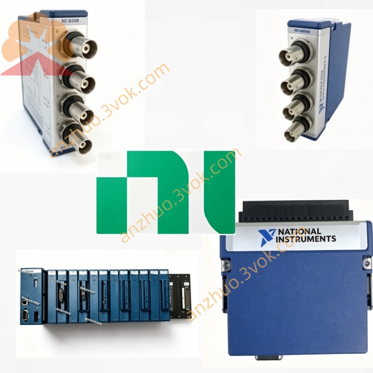
NI PXIe-2540 300MHz 4×8 RF Matrix Switch Module
The PXIe-2540 is a non-blocking RF matrix switch module built on the PXI Express platform. It features an 8×9 matrix with 72 crosspoints and operates from DC up to 350 MHz. Equipped with high-performance reed relays and MCX connectors, this module delivers excellent RF isolation and signal integrity. It is designed for flexible routing of radio frequency signals between signal generators, digitizers, spectrum analyzers and other RF test instruments, and is widely deployed in automated RF test systems.
Description
Model Nomenclature
PXIe represents the PXI Express high-speed modular instrumentation bus standard. The number 25 stands for NI switch and matrix product series. 2540 indicates an RF matrix switch with 8×9 topology, 350 MHz bandwidth and MCX interface layout.
Technical Specifications
This module adopts a standard 3U single-slot form factor and fits into PXIe hybrid or peripheral slots. It is configured as an 8-row by 9-column non-blocking matrix with 72 total crosspoints. It uses gold-plated reed relays optimized for RF performance. The operating frequency range covers DC to 350 MHz. The maximum switching voltage is 60 VDC or 42.4 V peak AC, and the maximum switching current is 0.5 A for both AC and DC signals. The typical on-resistance is less than 2.1 ohms. Built-in isolation relays maintain high crosstalk rejection across all channels. The maximum scan rate reaches 100 cycles per second. The mechanical relay life exceeds 10 million operations under rated conditions. The operating temperature ranges from 0 °C to 55 °C, and the storage temperature ranges from -20 °C to 70 °C. The typical power consumption of the module is approximately 10 watts.
Interface and Communication Configuration
The front panel is fitted with 17 female MCX connectors, including 8 ports for row channels and 9 ports for column channels. The module uses PXIe Gen1 bus and supports PXI trigger lines to achieve synchronous switching among multiple modules. The hardware trigger interface provides stable and deterministic control for test sequences. It is plug-and-play compatible with mainstream Windows operating systems. Users can complete hardware configuration, channel setup and status diagnosis via NI-MAX. Programming and secondary development are supported through LabVIEW, LabWindows/CVI and C++ APIs, together with the NI-SWITCH driver.
Core Features
It adopts a full non-blocking matrix structure, allowing any row channel to connect to any column channel simultaneously for flexible signal routing. Optimized RF circuit design and isolation relays ensure high isolation and low crosstalk in RF signal transmission. Compact MCX connectors save panel space and provide reliable radio frequency connection. The module supports multi-module cascading to expand the matrix scale for larger test systems. Reed relays offer long service life and stable performance, suitable for long-term continuous operation in mass production test lines. Hardware triggering enables precise and repeatable switching actions.
Application Scenarios
It is used for functional testing of wireless communication devices and modules within 350 MHz frequency range. It serves as signal routing equipment between RF signal generators, spectrum analyzers, oscilloscopes and other test instruments. It conducts RF parametric testing for semiconductor components. It applies to performance verification of automotive electronic modules and industrial communication equipment. It is also widely used in general-purpose RF automated test and measurement systems.
Usage and Maintenance Instructions
Installation and Configuration
Insert the module into a 3U single-slot PXIe chassis and fasten the front panel latch. Connect RF cables to corresponding MCX ports according to row and column definitions. Power on the chassis, and the system will automatically recognize the hardware. Launch NI-MAX to configure channel connections and trigger parameters. Develop and execute test programs using supported programming environments to implement automatic signal switching and testing.
Daily Maintenance
Keep the module and chassis in a clean, dry and well-ventilated environment within the rated temperature range. Avoid applying excessive force when plugging and unplugging MCX connectors to prevent mechanical damage. Inspect cables and connectors regularly for wear, dirt or poor contact. Ensure sufficient chassis cooling during long-time running. When the module is not in use for a long period, cut off the power, disconnect all cables and store it in a dry electrostatic protective environment.
Safety Notice
Do not apply voltage or current beyond the rated range to avoid permanent damage to relays and circuits. Follow standard electrostatic protection procedures when handling the module. Disconnect all power sources before installing, removing or servicing the device. Use qualified RF cables matching the working frequency. Dispose of the module in accordance with local electronic waste management regulations when it reaches the end of service life.
Get a Quote