
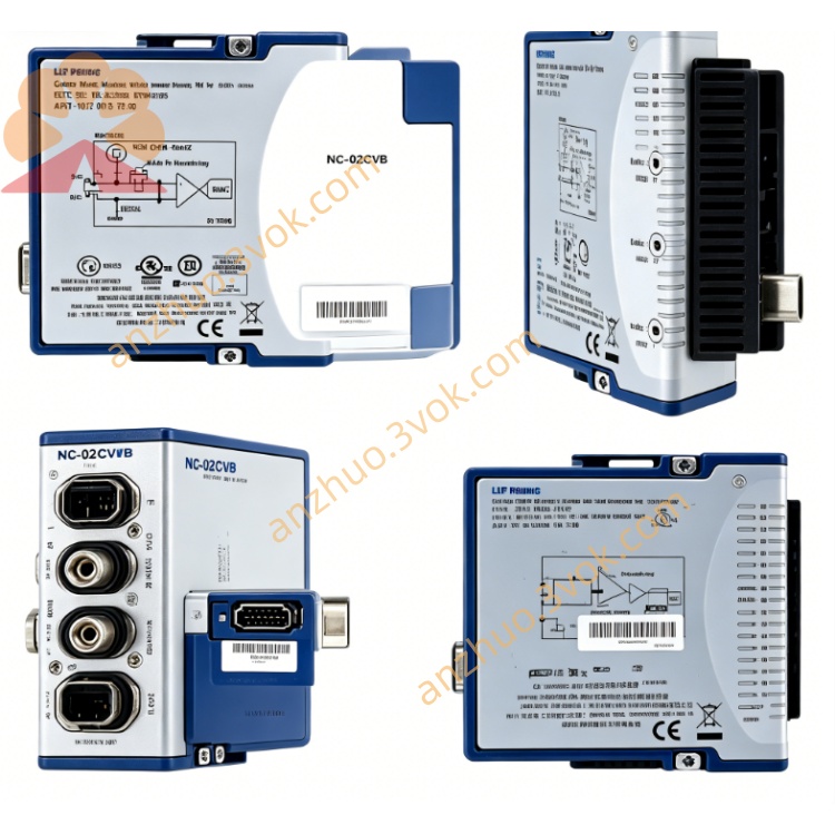
NI PXIe-2527 300V 32CH High Voltage Mux Switch
Description
Model Nomenclature
PXIe: PXI Express high‑speed modular instrument bus.
25: Series for switch/multiplexer modules.
27: High‑voltage multiplexer variant with 300 V rating, 32‑channel 2‑wire base configuration, and multi‑topology support.
Technical Specifications
Form factor: 3U, one‑slot PXIe.
Channel configurations: 64×1 (1‑wire), 32×1 (2‑wire), 16×1 (4‑wire)NI.
Relay type: Electromechanical, high‑power.
Max switching voltage: 300 VDC / 300 VAC (CAT I)NI.
Max switching current: 2 A DC / ACNI.
Minimum switch load: 20 mV, 1 mA.
Bandwidth: 30 MHz.
Scan rate: 140 cycles per secondNI.
On‑resistance: Typical <1 Ω per channel.
Relay life: >10⁶ operations at full rating.
Operating temperature: 0 °C to 50 °C; storage: −40 °C to 70 °C.
Power: 12 W (+12 V) via PXIe bus.
Interface and Communication Configuration
Front panel: Two high‑voltage D‑sub connectors for channel I/O and common terminals.
Bus: PXIe Gen1, PXI trigger lines 0–7 for multi‑module synchronization.
Trigger: Hardware trigger input for deterministic channel switching; minimum pulse width 150 ns.
Software: Plug‑and‑play for Windows; configured in NI‑MAX; programmable via LabVIEW, LabWindows/CVI, C++ APIs; supported by NI‑SWITCH driverNI.
Core Features
Flexible topology: Software‑selectable 1‑wire, 2‑wire, or 4‑wire multiplexing for voltage, current, and resistance measurementsNI.
High‑voltage capability: 300 V rating enables testing of industrial, aerospace, and automotive high‑voltage componentsNI.
Relay monitoring: Onboard relay counter tracks switching cycles for predictive maintenanceNI.
Deterministic triggering: Hardware triggers ensure precise, repeatable switching sequencesNI.
Transient suppression: Integrated protection extends relay life under inductive loads.
PXIe integration: Seamlessly synchronizes with PXI DMMs, SMUs, and other instruments for scalable test systemsNI.
Application Scenarios
Industrial automation and power electronics component testing.
Aerospace and defense high‑voltage subsystem validation.
Automotive battery, ECU, and high‑voltage distribution testing.
Semiconductor and passive device parametric test (high‑voltage).
Medium‑to‑high channel count data acquisition and signal routing.
Get a Quote