
PXIE-2515
May 27, 2026

PXIE-2515

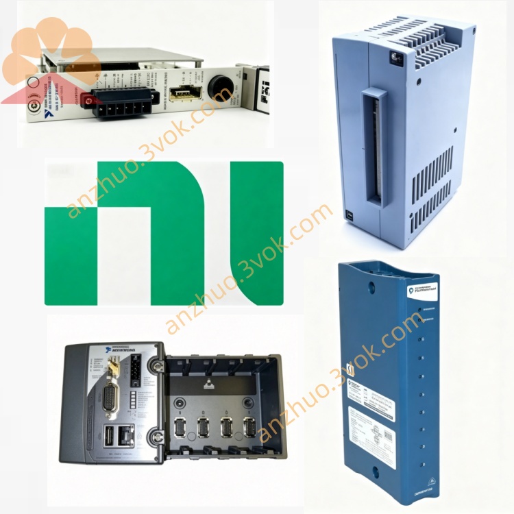
The PXIe-2515 (NI Part Number: 780587-15) is a 35‑channel high‑speed digital signal insertion switch module for PXI Express systems, designed by National Instruments. It is a 3U one‑slot multiplexer using reed relays, intended to route high‑speed digital I/O (DIO) signals between a device under test (DUT) and NI high‑speed DIO or parametric measurement instrumentsNI. It enables DC parametric tests on digital pins without external wiring or impedance mismatch issues, supporting one high‑speed DIO device plus up to two additional instruments via dual analog buses. With 30 VDC maximum voltage, 0.25 A per channel, and 50 MHz bandwidth, it targets digital test and parametric validation in semiconductor, aerospace, and industrial applications.

Description

Model Nomenclature

  • PXIe: PXI Express high‑speed modular instrument bus.

  • 25: Series identifier for switch/signal insertion modules.

  • 15: High‑speed digital multiplexer variant with 35 channels, reed relays, and dual analog buses for parametric measurement.

Technical Specifications

  • Form factor: 3U, one‑slot PXIe.

  • Channels: 35 channels (32 signal + 3 analog bus).

  • Relay type: Reed, rhodium contacts.

  • Max switching voltage: 30 VDC.

  • Max switching current: 0.25 A DC per channel.

  • Switch bandwidth: 50 MHz.

  • On‑resistance: Typically <2 Ω per channel.

  • Switching time: Typical 100 μs (including settling).

  • Relay life: >10⁸ operations under rated conditions.

  • Operating temperature: 0 °C to 50 °C; storage: -40 °C to 70 °C.

  • Power consumption: 8.4 W (+12 V), 0.8 W (+3.3 V) via PXIe bus.

  • Dimensions: 21.6 cm × 2.0 cm × 13.0 cm; weight: 247 g.

Interface and Communication Configuration

  • Front panel: Two VHDCI female connectors for DUT and instrument I/O, two BNC female connectors for analog bus monitoring.

  • Bus: PXIe Gen1, PXI trigger lines 0–7 for multi‑module synchronization.

  • Trigger: Input pulse width ≥150 ns; output pulse width software‑programmable 1–62 μs.

  • Software: Plug‑and‑play for Windows; configurable in NI‑MAX; programmable via LabVIEW, LabWindows/CVI, C++ APIs; supported by NI‑SWITCH driverNI.

Core Features

  • High‑speed digital routing: 50 MHz bandwidth for DIO signal switching and insertion.

  • Parametric test capability: Dual analog buses enable SMU/DMM connection for DC parametric measurements on digital pins.

  • Multi‑instrument integration: Connect one high‑speed DIO device (e.g., NI 654x/655x) and up to two instruments simultaneously.

  • Reed relay reliability: Fast, low‑contact‑resistance switching with long operational lifeNI.

  • Impedance control: Matched signal paths minimize reflections in high‑speed digital test systems.

  • PXIe synchronization: Align switching sequences with other PXIe instruments for coordinated test flows.

Application Scenarios

  • Semiconductor digital IC and SoC parametric and functional test.

  • Aerospace and defense avionics digital I/O validation and fault insertion.

  • Industrial control and embedded system digital pin characterization.

  • Automotive ECU and infotainment digital interface testing.

  • High‑speed digital board test and boundary scan validation.

Usage and Maintenance Instructions

Installation and Configuration

Insert the module into a 3U one‑slot PXIe chassis and secure the latch. Connect DUT cables to one VHDCI connector and instruments to the other VHDCI/BNC connectors, verifying channel and analog bus mapping. Power on the chassis; the system detects the module automatically. Use NI‑MAX to configure channel routing, analog bus assignments, and trigger parameters. Develop test sequences in LabVIEW or other supported environments to define switching patterns and parametric measurements. Verify all connections and impedance matching before applying signals to avoid reflections or damage.

Daily Maintenance

Keep the module and chassis clean, dry, and ventilated within rated temperature ranges. Avoid excessive force when mating VHDCI/BNC cables to prevent connector damage. Inspect cables and connectors periodically for wear, dirt, or loose contacts. Ensure adequate chassis cooling to prevent overheating, especially during continuous high‑bandwidth operation. Store in a dry, antistatic environment when not in use.

Safety Notice

Do not apply voltages exceeding 30 VDC or currents above 0.25 A per channel. Follow ESD procedures when handling the module to protect sensitive relays and circuitry. Disconnect all power before installation, removal, or servicing. Avoid switching inductive loads without transient suppression to prevent voltage spikes that damage relays. Dispose of according to local electronic waste regulations at end‑of‑life.


Get a Quote