
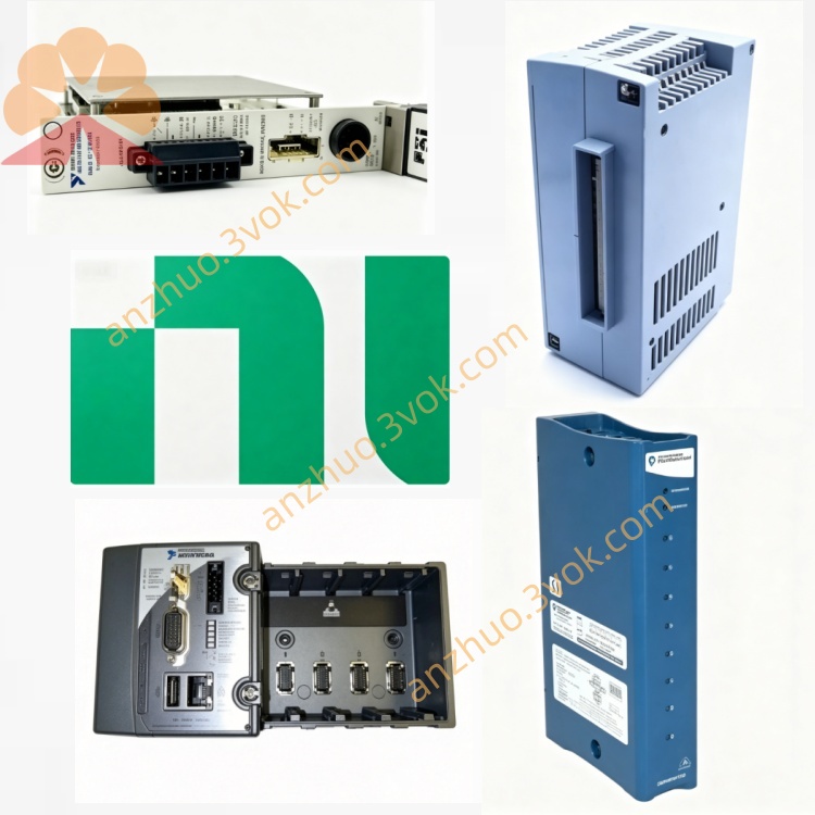
NI PXIe-2514 7CH 40A Fault Insertion Switch FIU
Description
Model Nomenclature
PXIe: PXI Express high-speed modular instrument bus.
25: Series identifier for switch/insertion modules.
14: High-current FIU variant with 7 channels, 40 A rating, and dual fault buses.
Technical Specifications
Form factor: 3U, two‑slot PXIe.
Channels: 7 independent feedthrough channels (FET relays).
Max switching voltage: 28 VDC.
Continuous current: 40 A per channel; pulsed current up to 100 A (short duration).
Bandwidth: 800 kHz (50 Ω system).
On‑resistance: typically 8 mΩ per channel.
Switching time: 8 μs typical, 35 μs maximum.
Relay life: unlimited under rated conditions.
Protection: overcurrent (42 A typical), overtemperature.
Operating temperature: 0 °C to 50 °C; storage: -40 °C to 70 °C.
Power: 18 W (+12 V) via PXIe busNI.
Interface and Communication Configuration
Front panel: two 8‑position male DSUB connectors for signal I/O and fault bus connectionsNI.
Bus: PXIe Gen1, PXI trigger lines 0–7 for multi‑module synchronization.
Trigger: input minimum pulse width 150 ns; output pulse width software‑programmable.
Software: plug‑and‑play for Windows; configurable in NI‑MAX; programmable via LabVIEW, LabWindows/CVI, C++ APIsNI.
Core Features
High‑current fault simulation: 40 A continuous, supporting high‑power ECU and actuator testing.
Per‑channel fault modes: open, pin‑to‑pin short, short to battery, short to ground.
Feedthrough design: normal operation transparent to DUT; faults injected on demand.
Fast FET switching: microsecond‑level actuation for real‑time HILNI.
Integrated protection: overcurrent and overtemperature safeguard DUT and moduleNI.
Seamless PXIe integration: synchronize with other PXIe instruments for HIL systems.
Application Scenarios
Automotive ECU, BMS, and power distribution HIL testing.
Aerospace FADEC and avionics fault injection validation.
Industrial control and power electronics reliability testing.
High‑power wiring harness and connector fault simulation.
Battery system and high‑voltage component verification.
Get a Quote