
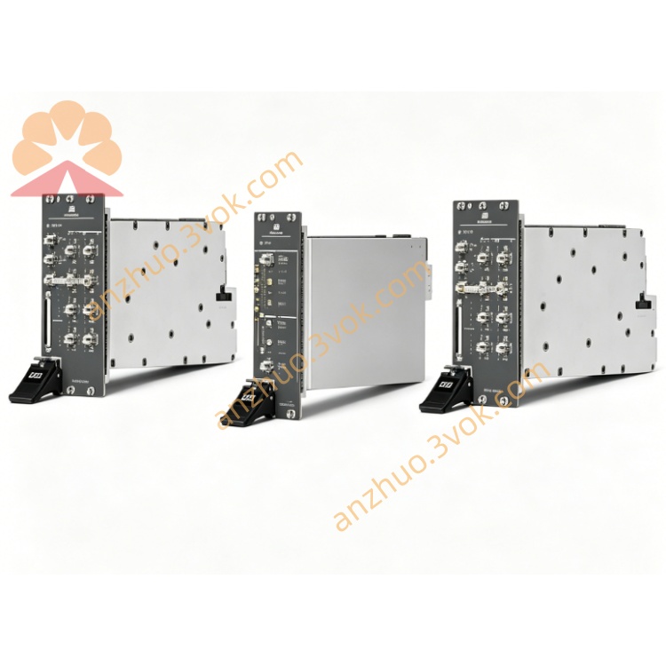
Astronics PXIe-2461 2CH 235MHz Counter/Timer
The PXIe-2461 is a 2-channel high-performance frequency and time interval counter module designed by Astronics and distributed by National Instruments. It is a single-slot 3U PXI Express device equipped with a high-stability oven-controlled crystal oscillator. This module supports comprehensive time and frequency measurement functions covering frequency, period, time interval, pulse characteristics, phase and voltage. With a maximum input frequency up to 235 MHz and wide input voltage range, it is well suited for high-precision timing, frequency analysis and general-purpose signal measurement in industrial, aerospace and automated test systems. The corresponding NI part number is 784197-01.
Description
Model Nomenclature
PXIe stands for PXI Express, the high-speed modular instrumentation bus standard. The number 2461 is the specific model code for this frequency and time counter series. This model is defined as a 2-channel counter with 235 MHz measurement bandwidth and ±42 V high-voltage input capability.
Technical Specifications
This module adopts standard 3U single-slot PXI Express form factor. It has two independent measurement channels with a frequency measurement range from DC to 235 MHz. The maximum frequency resolution reaches 9 digits per second with a lower limit of 600 microhertz. For time interval measurement, the single-shot resolution is 1 nanosecond, and the averaged mode achieves 100 picoseconds resolution. Two input voltage ranges are available, including low range of ±5.1 V and high range of ±42 V. The input impedance can be selected as 50 ohms or 1 megaohm via software configuration. The trigger sensitivity is adjustable from 2.5 millivolts to 25 millivolts, and programmable hysteresis is provided for noise suppression.
The measurable pulse width ranges from 5 nanoseconds to 20 milliseconds, while rise and fall time ranges from 20 nanoseconds to 20 milliseconds. The phase measurement resolution covers 0.1 degree to 360 degrees. It supports 11 automatic measurement functions and 9 arm trigger modes with programmable timeout setting. An onboard high-precision oven-controlled crystal oscillator serves as the reference clock. The module uses PXIe Gen1 bus interface with typical power consumption of 31 watts. The operating temperature range is 0 degrees Celsius to 55 degrees Celsius.
Interface and Communication Configuration
The front panel is fitted with two BNC connectors for signal input and one MCX connector for external reference clock and trigger signal. Input coupling can be set to DC coupling for DC to 235 MHz signals or AC coupling for 10 Hz to 235 MHz signals. The module supports PXIe trigger bus for multi-device synchronization and external clock input through the MCX port. It follows plug-and-play mechanism under mainstream Windows operating systems. Users can complete hardware configuration, function setup and status diagnosis via NI-MAX. Application development is available through LabVIEW, LabWindows/CVI and C++ programming interfaces.
Core Features
It integrates 11 types of automatic measurement functions to acquire frequency, period, time interval, pulse width, duty cycle, phase and voltage parameters efficiently. The wide ±42 V high-voltage input range allows direct measurement of industrial signals without external voltage divider. It delivers ultra-high time resolution to meet strict requirements of high-speed timing verification. Programmable trigger level and hysteresis enhance noise resistance for stable measurement in complex electromagnetic environments. The two independent channels support cross-correlation measurement such as phase difference and time delay between signals. It can be seamlessly integrated into existing PXIe test platforms for unified system deployment.
Application Scenarios
It is widely used for timing sequence verification and clock jitter test of semiconductor chips. It performs frequency and phase calibration for radio frequency and microwave modules. It applies to high-precision timing testing in aerospace and defense industries. It analyzes pulse signals and phase parameters for power equipment and motor control systems. It acts as a standard frequency and time measurement unit in various automated test equipment.
Usage and Maintenance Instructions
Installation and Configuration
Insert the module into any standard 3U PXIe slot and fasten the front panel latch. Connect measured signals to BNC ports, and link external reference clock or trigger signals to the MCX port if needed. Power on the PXIe chassis, and the system will automatically detect the new hardware. Launch NI-MAX to configure input voltage range, impedance, coupling mode and trigger parameters according to actual test demands. Develop and execute test programs with supported programming software. Pay attention to safety operation when measuring high-voltage signals.
Daily Maintenance
Keep the module and chassis in a clean and well-ventilated environment and operate within the specified temperature range. Avoid over-tightening BNC connectors during wiring and disconnection. Inspect cables and connectors regularly to prevent poor contact or damage. Perform periodic calibration for the onboard oven-controlled crystal oscillator with standard frequency sources to maintain measurement accuracy. Power off the device and disconnect all cables for long-term storage, and place the module in a dry environment.
Safety Notice
Do not apply signals exceeding the rated input voltage to prevent hardware damage. Follow electrostatic protection guidelines when handling the module. Disconnect all power sources before removing or replacing the module. Comply with local regulations for electronic waste disposal when the module reaches the end of service life.
Get a Quote