
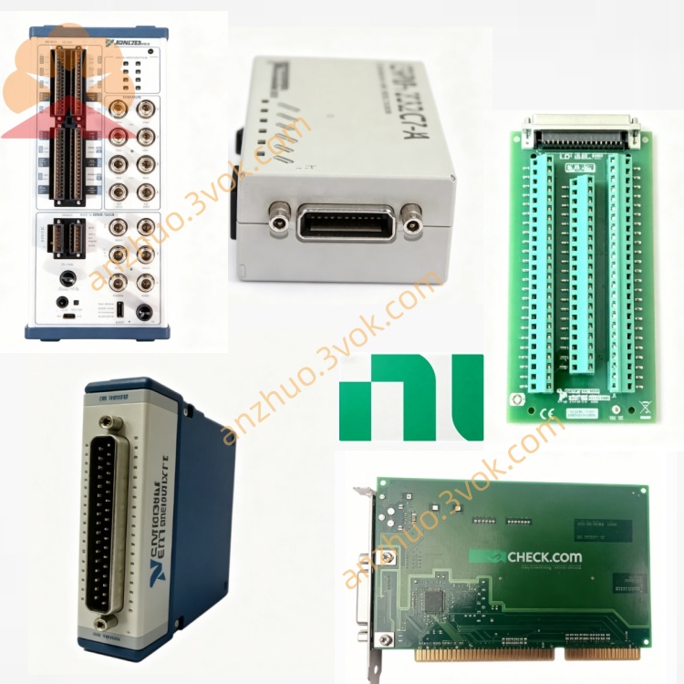
NI PXIe-1487 FlexRIO GMSL2 Automotive Camera Interface Module
Description
Model Nomenclature
PXIe: PCI Express extensions for Instrumentation, denoting PXI Express platform.
1487: NI’s product number for FlexRIO GMSL2 interface modules.
FlexRIO: Indicates FPGA‑based reconfigurable I/O architecture.
GMSL2: Gigabit Multimedia Serial Link 2, the high‑speed serial video standard used.
Configurations: 8I (deserializer), 8O (serializer), 4I/4O (SerDes); part numbers vary by channel count and function.
Technical Specifications
Form Factor: 3U PXI Express, single‑slot.
Bus Interface: PCIe Gen3 x8, up to 8 GB/s.
FPGA: Xilinx KU11P.
Memory: 4 GB DDR4 (2×2 GB), 267 MHz FPGA clock, 17 GB/s theoretical max throughputNI.
GMSL2 Links: Up to 8 channels; each up to 6 Gb/s.
Connectors: FAKRA Male Code Z (coaxial) for both input (SI) and output (SO)NI.
PoC Power:
Input (SI): 9–30 V, up to 800 mA per channel.
Output (SO): 12 V nominal, up to 400 mA per channel, 2 A totalNI.
Protocols: GMSL2, pixel mode, pixel tunneling mode.
Aux I/O: I²C back‑channel, GPIO per channel.
Operating Temperature: 0 °C to 55 °C.
Power: From PXIe backplane; typical <25 W.
Part Numbers: 787456‑01 (8I), 787457‑01 (8O), 787458‑01 (4I/4O), etc.
Interface and Communication Configuration
Front Panel: FAKRA Z connectors for GMSL2 video links; status LEDs for power, link lock, and activity.
GMSL2 I/O:
Inputs (SI): Receive serialized video from cameras; PoC output to power cameras.
Outputs (SO): Transmit serialized video to ECUs; accept PoC from ECU or internal 12 VNI.
Back‑Channel: I²C on each link for camera control, configuration, and diagnostics.
GPIO: Per‑channel GPIO for triggers, sensor reset, and synchronization.
Synchronization: PXIe trigger bus and PXI clock; supports multi‑module sync.
Software: NI‑MAX for configuration; FlexRIO driver; LabVIEW FPGA API for custom logic.
Core Features
High‑Speed GMSL2 Connectivity: Up to 8×6 Gb/s links for uncompressed video and sensor data.
Reconfigurable FPGA: User‑programmable Xilinx KU11P enables real‑time video processing, filtering, and protocol conversion.
Integrated PoC: Supplies or accepts power over coax, simplifying camera cabling in vehicles and test benchesNI.
Dual Control Channels: I²C and GPIO allow full camera/ECU configuration, monitoring, and triggering.
Flexible Channel Configurations: Choose 8‑in, 8‑out, or 4‑in/4‑out to match logging, replay, or HIL needs.
High Bandwidth Memory: 4 GB DDR4 supports large frame buffers and high‑throughput data recording.
PXIe Ecosystem Integration: Synchronizes with other PXIe instruments for mixed‑signal HIL and test systems.
Application Scenarios
ADAS/AD HIL Testing: Emulate or capture multiple camera feeds for ECU validation in autonomous driving systems.
In‑Vehicle Data Logging: Record raw GMSL2 video from 4–8 cameras during road tests.
Lab‑Based Playback: Replay recorded camera streams to ECUs for regression and edge‑case testing.
Camera Validation: Test camera modules, firmware, and link stability under noise and voltage variation.
Multi‑Sensor Fusion: Synchronize video with LiDAR, radar, and CAN data in a unified PXIe system.
Usage and Maintenance Instructions
Installation and Configuration
Insert the module into a 3U PXIe Gen3 slot and secure the ejector.
Connect FAKRA cables between SI/SO ports and cameras/ECUs; ensure correct PoC voltage and polarity.
Power on the chassis; install FlexRIO drivers and LabVIEW FPGA support.
In NI‑MAX, configure link count, GMSL2 mode (pixel/tunneling), PoC voltage/current limits, and I²C/GPIO settings.
Deploy FPGA bitfiles and application code for logging, replay, or real‑time processing.
Validate link lock and data integrity using built‑in diagnostics and example projects.
Daily Maintenance
Inspect FAKRA connectors and cables daily for wear, dirt, or loose contacts.
Verify link status LEDs and error counters in NI‑MAX after each test session.
Keep the chassis and module clean; avoid blocking front‑panel airflow.
Check PoC voltage and current limits monthly to prevent overstress.
For long‑term storage, power off, disconnect cables, and store in a dry, ESD‑safe environment.
Safety Notice
Do not exceed specified PoC voltage (9–30 V) or current limits to avoid damage to cameras or the module.
Use ESD precautions when handling the module and cables.
Disconnect power before inserting/removing the module or attaching/detaching FAKRA cables.
Follow local regulations for disposal of electronic waste at end‑of‑life.
Get a Quote