
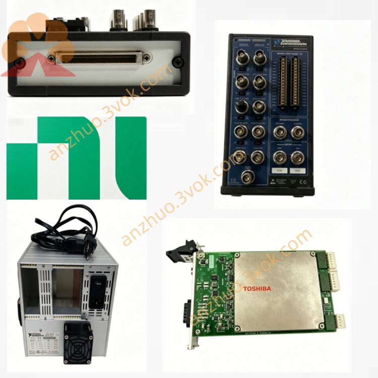
NI PXI-8532 1-Port DeviceNet Industrial Communication Module
The PXI‑8532 is a 1‑port DeviceNet communication module for 3U PXI systems (part number 781063‑01). It turns a PXI chassis into a DeviceNet master (scanner) or slave, enabling connection to third‑party DeviceNet networks in industrial automation. Built on CAN physical layer, it uses the NI‑Industrial Communications for DeviceNet driver.
Description
Model Nomenclature
PXI stands for PCI eXtensions for Instrumentation, referring to the 3U modular instrumentation bus standard. The series number 8532 represents NI’s DeviceNet interface product line. This module features one independent DeviceNet port and is built upon CAN bus technology optimized for industrial protocol operation.
Technical Specifications
This module adopts the standard 3U form factor and occupies one slot inside a PXI chassis. It is equipped with one DeviceNet port that follows standard DeviceNet specifications. Three standard baud rates are supported, including 125 kbps, 250 kbps and 500 kbps. It uses PCA82C251 transceiver compliant with ISO 11898 standards. The module provides 500 VDC galvanic isolation between the communication channel and the bus side to resist voltage surges and ground loop interference. A DB-9 male connector is arranged on the front panel for external wiring. An embedded on-board microprocessor handles protocol processing independently. The module draws power from the 5 V power rail of the PXI backplane. The operating temperature ranges from 0 degrees Celsius to 55 degrees Celsius. It is compatible with Windows operating systems and LabVIEW Real-Time, and works with NI-Industrial Communications for DeviceNet, LabVIEW, LabWindows/CVI, C/C++ and Python development tools.
Interface and Communication Configuration
The front-panel DB-9 connector is used to connect standard DeviceNet cables and field devices. The module supports plug-and-play recognition under mainstream operating systems. Users can set the operating mode as master scanner or slave node, baud rate and node address independently via configuration tools. Proper bus termination shall be deployed on both ends of the DeviceNet cable to ensure signal integrity. All network parameters and communication settings can be configured and diagnosed through NI-MAX. It supports explicit messaging and cyclic I/O data transmission defined by the DeviceNet protocol.
Core Features
It supports two working modes, master scanner and slave node, to meet different requirements of network control and device emulation. The 500 VDC galvanic isolation effectively protects the module and host system from harsh electrical conditions on industrial sites. Inheriting the fault tolerance and anti-interference capability of CAN physical layer, it delivers stable operation in complex industrial electromagnetic environments. The built-in processor processes protocol tasks locally and reduces the load of the host controller. It provides complete application programming interfaces to implement network management, data reading and writing, and device diagnosis.
Application Scenarios
It is widely used in industrial automation to connect PXI systems with DeviceNet-based PLCs, remote I/O modules, sensors and actuators. It serves as network management equipment for monitoring and maintaining on-site DeviceNet networks on production lines. It is applied to industrial test benches for function verification and performance testing of DeviceNet field devices. It can also be used for equipment development and protocol verification during the research and prototyping phase of new industrial products.
Usage and Maintenance Instructions
Installation and Configuration
Insert the module into any available 3U PXI slot and fasten the front panel securely. Connect DeviceNet cables between the DB-9 port and field devices, and install termination resistors at both ends of the bus. Power on the PXI chassis, and the system will automatically detect the new hardware. Install the corresponding NI-Industrial Communications for DeviceNet driver software. Open NI-MAX to configure working mode, baud rate and node address according to on-site network requirements. Develop and run communication applications with LabVIEW or other supported programming environments.
Daily Maintenance
Check DB-9 connectors and cables regularly to prevent poor contact, wear or damage. Keep the PXI chassis and module in a clean and dry environment, and operate within the specified temperature range. Do not plug or unplug cables or the module when the system is powered on. For long-term idle modules, store them in anti-static bags under dry conditions. Conduct routine inspection on bus termination status to avoid abnormal signal transmission.
Safety Notice
Do not operate the module beyond its rated isolation voltage and environmental limits. Follow local electronic waste management regulations to recycle or dispose of the module when it reaches the end of service life.
Get a Quote