
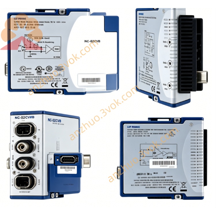
NI PXI-8516 2-Port LIN Bus Interface Module
Description
Model Nomenclature
PXI: 3U PXI modular instrumentation bus
8516: NI LIN interface series
/2: 2‑port configuration (only variant, P/N 781366‑01)
Technical Specifications
Form factor: 3U, single‑slot PXI
Ports: 2 × LIN 2.0/2.1/2.2 (single‑wire, 12 V)
Transceiver: Atmel ATA6620 (rev F and earlier) / ATA6625 (rev G+)
Baud rate: 2.4 kbps to 20 kbps (software configurable)
Connectors: 2 × DB‑9 male (front panel)
Isolation: None (LIN is single‑wire, ground‑referenced)
DMA: Onboard DMA engine, zero CPU interrupt for frame transfer
Latency: Typical <100 µs
Timestamping: 1 µs precision
Bus voltage: LIN bus requires +8 VDC to +18 VDC (external supply)
Power: +3.3 VDC (940 mA) from PXI backplane
Operating temperature: 0 °C to 55 °C; storage –20 °C to 70 °C
Software: NI‑XNET, LabVIEW, LabWindows/CVI, C/C++, Python, VeriStand
OS: Windows 7/10/11, LabVIEW Real‑Time
Interface and Communication Configuration
Front‑panel DB‑9 male connectors for LIN bus cables (single‑wire LIN + ground)
Each port independently configurable for baud rate, master/slave mode, and scheduling
Supports listen‑only mode for passive bus monitoring
RTSI/PXI trigger bus integration (7 in/out trigger lines, 1 in/out clock line) for multi‑module synchronization
Termination: No external termination required (LIN uses internal pull‑up)
Configuration via NI‑MAX or NI‑XNET API; supports LDF (LIN Description File) database import
Core Features
Dual‑port LIN: Two independent LIN interfaces for simultaneous testing of multiple LIN subnets
Multi‑protocol LIN: Native support for LIN 2.0/2.1/2.2, compatible with most automotive body ECUs
NI‑XNET DMA: Offloads LIN frame processing from CPU, reducing latency and jitter
Master/slave support: Hardware‑timed scheduling for master tasks; slave mode for ECU emulation
LDF database support: Direct import of LIN signals and schedules for rapid application development
Application Scenarios
Automotive body electronics: Testing door, window, lighting, and climate ECUs on LIN buses
HIL simulation: Real‑time emulation of LIN‑based body systems in vehicle test benches
Rapid control prototyping: Validating LIN communication for new ECU designs
Industrial automation: Low‑speed sensor/actuator networks in factory equipment
Bus monitoring and diagnostics: Logging and analyzing LIN traffic for R&D and production
Usage and Maintenance Instructions
Installation and Configuration
Insert the module into any 3U PXI slot and secure the front panel.
Connect LIN bus cables to DB‑9 ports; ensure external +8–18 VDC power is supplied to the LIN bus.
Power on the chassis; Windows automatically detects the hardware.
Install the NI‑XNET driver and configure baud rate/master‑slave mode in NI‑MAX.
Develop applications using LabVIEW or C/C++ with the NI‑XNET API; import LDF files for signal‑level access.
Daily Maintenance
Inspect DB‑9 connectors and cables for damage or loose pins.
Verify LIN bus voltage is within +8–18 VDC range.
Operate within 0–55 °C; keep the chassis clean and dry.
Avoid hot‑swapping the module or LIN cables during operation.
Store unused modules in anti‑static bags in a cool, dry place.
Safety Notice
Do not apply voltage outside +8–18 VDC to the LIN bus.
Follow local regulations for disposal at end‑of‑life.
Get a Quote