
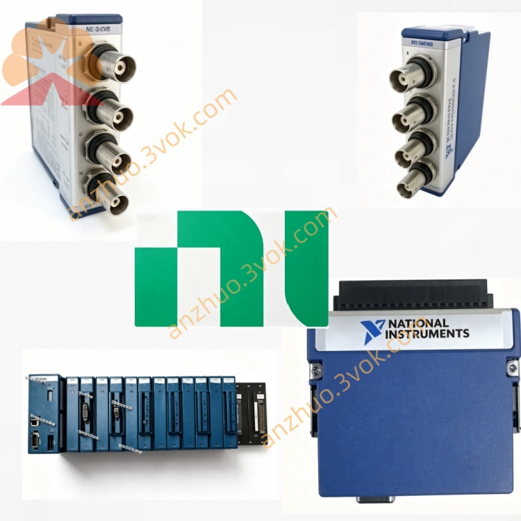
NI PXI-8511 Single-Port High-Speed CAN Interface Module
Description
Model Nomenclature
PXI: 3U PXI modular instrumentation bus
8511: NI low‑speed/fault‑tolerant CAN interface series
/1: 1‑port configuration (PXI‑8511/1, PN 780686‑01)
/2: 2‑port configuration (PXI‑8511/2, PN 780686‑02)
Technical Specifications
Form factor: 3U, single‑slot PXI
Ports: 1 or 2 × low‑speed/fault‑tolerant CAN 2.0A/B (ISO 11898‑3)NI
Transceiver: NXP TJA1054A (fault‑tolerant)
Baud rate: 40 kbps to 125 kbps
Connectors: 1 or 2 × DB‑9 male (front panel)
Isolation: 1 kVrms channel‑to‑chassis isolation
DMA: Onboard DMA engine, zero CPU interrupt for frame transferNI
Latency: Typical <50 µs
Message filtering: Advanced hardware filtering per port
Bus voltage range: CAN_H/CAN_L –27 VDC to +40 VDC
Power: +5 VDC from PXI backplane; 1‑port ~640 mA, 2‑port ~940 mA
Operating temperature: 0 °C to 55 °C; storage –20 °C to 70 °C
Software: NI‑XNET, LabVIEW, LabWindows/CVI, C/C++, Python, VeriStand
OS: Windows 7/10/11, LabVIEW Real‑Time
Interface and Communication Configuration
Front‑panel DB‑9 male connectors for standard CAN cables
Each port independently configurable for baud rate, filtering, and CAN 2.0A/B mode
Supports listen‑only mode for passive bus monitoring
No external trigger/sync connector (hardware limitation)
Termination: Requires external 120 Ω termination resistors at both ends of the bus
Configuration via NI‑MAX or NI‑XNET API; supports DBC/FIBEX/NCD CAN database import
Core Features
Fault‑tolerant CAN: Automatically detects and recovers from wiring faults, ensuring communication continuity
1 kVrms isolation: Protects PXI chassis from ground loops and voltage transients
NI‑XNET DMA: Offloads CAN frame processing from CPU, reducing latency and jitterNI
Low‑speed robustness: Optimized for 125 kbps and below in harsh industrial environments
Real‑time performance: Precise 1 µs timestamping for accurate event correlation
Application Scenarios
Automotive body electronics: Low‑speed CAN networks (e.g., lighting, door modules)
Industrial automation: Fault‑resilient CAN buses in factory floor equipment
Commercial vehicles: Truck/bus CAN systems requiring high fault tolerance
Hardware‑in‑the‑loop (HIL): Real‑time simulation of low‑speed CAN ECUsNI
Bus monitoring and diagnostics: Passive logging of fault‑prone CAN networks
Usage and Maintenance Instructions
Installation and Configuration
Insert the module into any 3U PXI slot and secure the front panel.
Connect CAN cables to the DB‑9 ports and external CAN nodes; add 120 Ω termination at bus ends.
Power on the chassis; Windows automatically detects the hardware.
Install the NI‑XNET driver and configure ports in NI‑MAX.
Develop applications using LabVIEW or C/C++ with the NI‑XNET API.
Daily Maintenance
Inspect DB‑9 connectors and cables for damage or loose pins.
Ensure proper bus termination (120 Ω) to avoid signal reflection.
Operate within 0–55 °C; keep the chassis clean and dry.
Avoid hot‑swapping the module or CAN cables during operation.
Store unused modules in anti‑static bags in a cool, dry place.
Safety Notice
Do not exceed the 1 kVrms isolation rating or –27 VDC to +40 VDC bus voltage limits.
Follow local regulations for disposal at end‑of‑life.
Get a Quote