
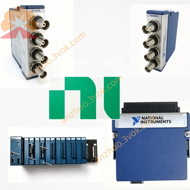
NI PXI-8331 MXI-4 Copper PXI Extension Controller Card
Description
Model Nomenclature
PXI: PCI eXtensions for Instrumentation, compliant with PXI modular instrumentation standard.
8331: Denotes MXI‑4 4th‑generation multi‑system extension interface; 1 indicates copper‑based variant (8336 is fiber‑optic version).
MXI‑4: Multi‑system Extension Interface, 4th generation, a hardware PCI‑to‑PCI bridge protocol.
Technical Specifications
General
Form Factor: 3U PXI, single‑slot.
Host Interface: PCI bus (PXI backplane).
Protocol: MXI‑4 (hardware PCI‑to‑PCI bridge).
Peak Bandwidth: 132 MB/s.
Sustained Bandwidth: 78 MB/s.
Serial Data Rate: 1.5 Gbit/s.
Max Links: Up to 254 (BIOS/System dependent).
Topology: Daisy‑chain or star configurations.
Cable & Distance
Copper Cable: 2 m, 5 m, 10 m options.
Fiber‑Optic Cable (PXI‑8336): Up to 200 m (multi‑mode).
Electrical & Environmental
Power: +5 VDC, 1.5 A (from PXI backplane).
Dimensions: 10.0 × 16.0 cm (3.9 × 6.3 in).
Operating Temperature: 0 °C to 50 °C.
Storage Temperature: −20 °C to 70 °C.
Humidity: 10%–90%, non‑condensing.
Interface & Communication Configuration
MXI‑4 Front‑Panel Connector: High‑speed serial port for copper/fiber cable connection.
Hardware PCI‑to‑PCI Bridge: Transparent link, no programming required for basic operation.
Trigger & Interrupt Routing: Passes PXI trigger bus and RTSI signals for multi‑chassis synchronization.
Error Checking & Retransmission: MXI‑4 protocol includes CRC and automatic retransmission for reliability.
LED Indicators: Power, link status, and activity LEDs for diagnostics.
Core Features
- Transparent PCI Bus ExtensionActs as a hardware PCI‑to‑PCI bridge; remote PXI modules are enumerated and controlled by the host as if local, requiring no driver‑level programming.
- MXI‑4 Reliability & EfficiencyImproved over MXI‑3: adds error checking and retransmission, higher sustained throughput, and better noise immunity for industrial environments.
- Long‑Distance & Isolation OptionsFiber‑optic (PXI‑8336) extends reach to 200 m and provides electrical isolation for high‑EMI settings.
- Multi‑Chassis & Mixed‑Bus SupportConnects PC ↔ PXI, PXI ↔ PXI, and legacy PXI ↔ VXI systems for large‑scale distributed test architectures.
- Software Transparency & OS CompatibilityWorks with Windows 7/10 and LabVIEW RT; NI‑PXI drivers enable advanced features like trigger routing and interrupt handling.
Application Scenarios
Distributed ATE Systems: Host in control room, PXI chassis on production lines for remote test execution.
High‑EMI Industrial Environments: Power plants, rail transit, and manufacturing floors using fiber isolation.
Multi‑Chassis PXI Test Systems: Scalable architectures for semiconductor, aerospace, and automotive testing.
Legacy System Integration: Connecting older PXI/VXI systems to modern PCs without rewriting software.
Usage & Maintenance Instructions
Installation
Insert the module into a 3U PXI chassis (e.g., PXI‑1042/1045), preferably near the system slot.
Connect the MXI‑4 copper cable between PXI‑8331 and a PCI‑8331/PXI‑8331 module in the host or another chassis.
Power on the chassis; the system automatically enumerates the MXI‑4 link and remote PCI devices.
Configuration
Enable MXI‑4 support in the system BIOS and configure PCI memory windows.
Install NI‑PXI Platform Services (v15.0 or later) for full functionality.
Maintenance
Periodically inspect cables and connectors for damage or loose connections.
Operate within specified temperature/humidity ranges and keep the chassis clean and dry.
For EOL hardware, maintain spare modules and cables to avoid downtime.
Troubleshoot using front‑panel LEDs and NI diagnostic tools for link or communication issues.
Get a Quote