
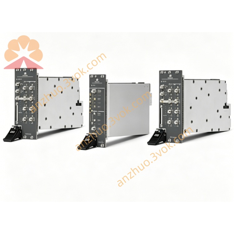
NI PXI-6652 PXI Timing and Synchronization Module
Description
II. Model Interpretation
PXI: Standard 3U single slot, compatible with PXI/PXIe mixed slots, supports PXI backplane clock, trigger, and star trigger bus.
6652: 665x Precision Timing Series, 2 represents the TCXO master clock model, with an internal temperature-compensated crystal oscillator, can be used as a master / slave.
Positioning: Medium stability master clock, balancing accuracy and cost, suitable for most industrial and testing scenarios.
III. Technical Parameters (25℃)
1. Clock and Frequency
Built-in reference: TCXO 10 MHz, stability 1 ppm
DDS output: DC ~ 105 MHz, resolution 1 μHz
External clock input: 1 MHz ~ 105 MHz, supports sine / square wave
Input impedance: 50 Ω
Phase synchronization accuracy: multi-box **<5 ns**
2. Trigger and Synchronization
Programmable PFI: 2 channels (SMB), input/output configurable
Backplane bus: controls 8 PXI_TRIG, PXI_STAR star trigger
Clock routing: supports receiving / forwarding / replacing the box backplane clock for PXI_CLK10
3. Physical and Environmental
Form: 3U single slot
Connectors: front panel 3×SMB (CLKIN, PFI0, PFI1)
Status indication: 2 groups of three-color LEDs (power / lock / activity)
Operating temperature: 0 ℃ ~ 55 ℃
Preheating time: 15 minutes (before calibration)
IV. Interface and Communication Configuration
1. Hardware Interface
Front panel: CLKIN (SMB), PFI0/PFI1 (SMB), 50 Ω impedance
Backplane: connects to PXI bus, links 10 MHz reference, trigger bus, star trigger
2. Software and Drivers
Driver: NI-SYNC, responsible for clock configuration, routing, and synchronization management
Development environment: supports LabVIEW, C/C++, Python, TestStand
Function: supports FPGA programming, customizes synchronization logic
V. Core Functions
10 MHz master clock output (TCXO)
Built-in 1 ppm temperature-compensated crystal oscillator, generates stable 10 MHz reference, can replace the box backplane clock, improves system timing accuracy.
High-resolution DDS clock generation
Output DC~105 MHz programmable clock, 1 μHz resolution, suitable for high-speed acquisition, RF testing, etc. precise timing requirements.
Flexible clock / trigger routing
Front panel and backplane signals freely mapped, supports external → PXI → external cascading, builds complex synchronization topology.
Master-slave mode switching
Can be used independently as a master clock, or receive an external 10 MHz reference as a slave, suitable for single-box or multi-box expansion scenarios.
Nanosecond-level multi-device synchronization
Combined with star trigger and dedicated synchronization circuit, realizes timing alignment of multiple boards, multiple boxes **<5 ns**.
VI. Application Scenarios
Mid-to-high-end PXI automated testing (ATE)
Multiple boards / multiple boxes systems, provide a stable 10 MHz reference, ensures consistent acquisition and output timing.
RF / microwave testing system
Provides 10 MHz reference for signal sources, spectrum analyzers, receivers, etc., realizes synchronization between instruments.
High-speed data acquisition
Multiple digital instruments, high-speed I/O cards linked, eliminates timing deviations, ensures synchronous acquisition accuracy.
Distributed industrial measurement and control
Collaboration of multiple sites, multiple-box industrial control equipment, unified actions and acquisition timing.
Semiconductor testing
Medium-precision timing verification, provides a synchronous trigger and clock reference for test units. VII. Installation and Maintenance Instructions
1. Installation and Power On
Disconnect and insert the PXI chassis (preferably Slot 2), tighten the screws and ensure reliable grounding. After powering on, perform self-check and observe the LEDs to confirm normal operation; maintain ventilation during operation to avoid temperature accumulation affecting stability.
2. Wiring and Operation
Interface: Use 50 Ω SMB shielded cable; for high-frequency (>10 MHz) signals, try to keep the lengths equal to reduce skew.
Mode: Default is the master mode (output 10 MHz); when switching modes, configure the software to receive an external reference.
Configuration: Set the DDS frequency, PFI direction, signal routing, and the synchronization logic can be programmed.
3. Daily Maintenance
Regularly clean the SMB interface, check the cable connections, and add dust caps for long-term inactivity.
There is no need for frequent calibration; it is recommended to do once a year using NI Calibration Executive, requiring 15 minutes of preheating.
Regularly update the NI-SYNC driver and firmware to ensure compatibility and stability.
Get a Quote