
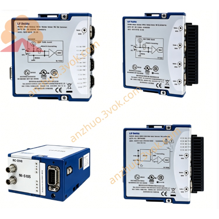
NI PXI-6602 8-Channel Counter/Timer DAQ Module
Description
II. Model Interpretation
PXI: 3U single-slot PXI module, compatible with PXI/PXIe mixed slots, standard PXI trigger bus.
6602: 660x (Timing/Counting + DIO series); 2 = 8-channel 32-bit counter, 80MHz base frequency, 3 DMA channels (6601 has 4 channels, 20MHz, 1 DMA channel).
Core Identifier: 8×32-bit counter, 80MHz (pre-divided by 125MHz), 32 5V DIO channels, 3 DMA channels, debouncing filtering, PXI synchronization.
III. Technical Parameters (25℃, PXI chassis)
Counter / Timer
Channels: 8 independent 32-bit add/subtract counters, maximum count value 2³² - 1.
Base Frequency: 100kHz/20MHz/80MHz (software selectable); pre-divided (×2/×8) up to 125MHz.
Input: 5V TTL/CMOS, low level -0.3~0.8V, high level 2.0~5.5V; minimum pulse width 5ns.
Measurement Function: Event counting, period/frequency, pulse width, duty cycle, quadrature encoder (4 times frequency) NI.
Output Function: single pulse, pulse sequence, PWM, retriggerable pulse; maximum output 40MHz.
Accuracy: temperature drift 75ppm (±0.0075%); long-term stability 20ppm/year.
Digital I/O
Channels: 32 5V TTL/CMOS bidirectional DIO; 8 dedicated, 24 shared with counters.
Level: input -0.3~5.5V, output 0~5V; single channel drive ±4mA.
Filtering: per-channel programmable digital debouncing / anti-windup (100ns~100ms) NI.
Transmission: static I/O, supports handshake; maximum 20MHz throughput.
Physical and Environmental
Size: 3U single-slot (160×100mm).
Power Consumption: +5V@0.5~1.5A, typical 7.5W.
Connector: 68-pin SCSI-II shielded male connector, with lock.
Temperature: 0~55℃ (commercial); extended grade -40~+85℃.
Synchronization: PXI trigger bus (6 wires), STAR trigger, external PFI.
IV. Interface and Communication Configuration
Hardware Interface
I/O: 68-pin SCSI-II, including 8 groups of counters (SOURCE/GATE/UPDN/OUT) + 32 DIO + power / ground.
Trigger: PXI backplane trigger bus, STAR trigger, external PFI, supports multi-module nanosecond-level synchronization.
Bus: PXI, 3 independent DMA (scatter-gather), supports high-speed data transmission, low CPU usage.
Software and Drivers
Driver: NI-TIO, paired with Counter/Timer Panel and Digital Waveform Editor.
Development Environment: LabVIEW, Python, C/C++, TestStand; supports scripted sequences, encoder decoding, PWM generation.
Synchronization: seamless synchronization with PXIe digitizers, AWGs, switches, power supplies, building mixed-signal ATE.
V. Core Functions
8-channel 32-bit high-speed counting / timing: 8 independent counters, 80MHz base frequency + 125MHz pre-divided, precise measurement of period/frequency/pulse width; Support orthogonal encoder 4x frequency, capture motor position/velocity NI.
32 channels 5V TTL/CMOS DIO + anti-jitter: 32 bidirectional DIO, 8 dedicated + 24 multiplexed; programmable digital filtering to eliminate contact jitter / spikes, suitable for industrial switches / sensors.
3 channels DMA high-speed transmission: simultaneous 3 DMA channels, zero CPU intervention, continuous acquisition / generation of pulse sequences, suitable for high-speed event recording, PWM closed-loop control.
Multifunctional pulse generation: single pulse, continuous pulse string, PWM (up to 40 MHz), retriggerable pulse; supports frequency keying FSK, phase modulation.
PXI bus precise synchronization: PXI trigger / STAR trigger, multi-module synchronization accuracy < 10ns; suitable for multi-axis motion control, multi-channel timing calibration, distributed testing.
Six, applicable scenarios
Industrial motion control: servo / stepper motor encoder position / speed feedback, limit switch counting, PWM speed control, pulse direction control NI.
Automation testing (ATE): PCB functional test event counting, frequency / period measurement, pulse generation, relay control, sensor signal acquisition.
Timing and communication testing: digital circuit timing verification, pulse width / duty cycle testing, FSK / Manchester encoding generation.
Automotive electronics: vehicle ECU pulse signal measurement, speed counting, PWM dimming / motor control, sensor pulse acquisition.
Research and laboratory: photon counting in physical experiments, particle detection, high-precision timing measurement, laser pulse triggering.
Seven, usage and maintenance instructions
Installation and power-on
Installation: disconnect power, insert into 3U slot of PXI chassis, chassis reliably grounded, anti-static operation; tighten the fixing screws.
Power-on: NI-TIO automatically self-checks after startup, no preheating required; avoid frequent cold-hot restarts.
Environment: keep the air duct unobstructed, 0~55℃; away from strong electromagnetic interference (motors, frequency converters).
Connection and operation
Connection: 68-pin SCSI-II to avoid frequent plugging and unplugging, use dedicated shielded cable; ensure impedance matching for long-distance transmission.
Level matching: confirm DUT is 5V TTL/CMOS, prohibit mixing with LVDS/RS-422 to prevent module damage.
Counter configuration: use differential lines / shielded lines for high-frequency signals (>1 MHz); enable digital anti-jitter for low-frequency signals (1~10ms).
Daily maintenance
Interface: regularly clean 68-pin interface, prevent dust and moisture; install dust cover when idle.
Software: update NI-TIO driver and firmware to obtain function optimization and bug fixes.
Calibration: no need for regular calibration (digital circuit); check wiring tightness, cable integrity and connector oxidation once a year.
Get a Quote