
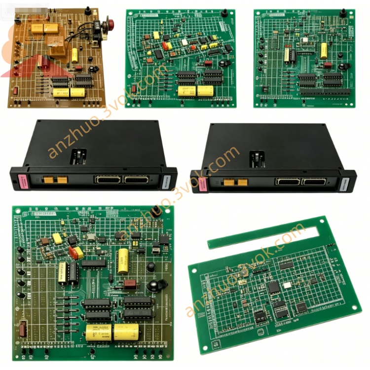
NI PXI‑2568 40‑Channel SPST PXI Relay Module
Description
II. Model Interpretation
PXI: Compliant with the PXI industrial bus standard, supporting installation and use in PXIe mixed slots
2568: The model code of the NI universal relay module series, representing a 32-channel SPDT universal electromechanical relay
Full name: PXI-2568 32-Channel SPDT PXI Relay Module
Topology identifier: NISWITCH_TOPOLOGY_2568_32_SPDT, the hardware topology is fixed and does not support software reconfiguration
III. Technical Parameters
(1) Switching and Electrical Characteristics
Topology: 32 independent SPDT (Form C), each channel includes a common terminal COM, a normally open terminal NO, and a normally closed terminal NC
Relay type: Electromechanical non-latching relay, with gold-plated contacts
Maximum switching voltage: 150 VDC / 125 VAC (CAT I safety level)
Maximum switching/carrying current per channel: 2 A
Maximum switching power: 60 W DC, 62.5 VA AC (power frequency)
On-state resistance: Typical value < 50 mΩ
Thermal offset: Typical value < 1 µV
Operating bandwidth: DC ~ 10 MHz
Action time: Typical 2 ms, maximum 4.4 ms
Insulation withstand voltage: Channel-to-channel, channel-to-ground withstand voltage 150 Vrms
(2) Life and Scan Parameters
Mechanical life: 2×10⁷ on-off cycles
Full-load electrical life: 1×10⁵ on-off cycles
Scan list: Maximum support 1024-step programmable scan sequence
Full-channel scan rate: Maximum 115 times/second
(3) Trigger and Control
Trigger channels: Support hardware trigger bus from PXI backplane Trigger 0 to Trigger 7
Minimum trigger pulse width: 150 ns
Board-level functions: Each relay channel is equipped with an independent counter unit for life monitoring
(4) Physical and Environmental Parameters
Form specification: Standard 3U PXI single-slot module
Front-end connector: 78-pin D-SUB female connector
Form size: 216 mm × 20 mm × 130 mm
Weight: Approximately 0.32 kg
Power supply method: 5 V power supply from PXI backplane, typical power consumption 5.0 W
Operating temperature: 0 ℃ ~ 55 ℃
Storage temperature: -20 ℃ ~ 70 ℃
Relative humidity: 5% ~ 85%, no condensation
IV. Interface and Communication Configuration
Front-end I/O Interface
All external signals of the module are centralized and led out through the 78-pin D-SUB female connector, including 32 complete SPDT signal channels (COM/NO/NC), and the remaining pins are shielding ground and reference ground. All channels are electrically isolated from each other, and a single channel failure will not affect the normal operation of other channels.
Bus and Software Communication
Bus interface: Standard PXI backplane bus, automatically acquires power, clock, and trigger signals, compatible with PXIe chassis mixed slots.
Driver: Standard NI-SWITCH driver, compliant with IVI instrument driver specification.
Software support: Compatible with mainstream development environments such as LabVIEW, TestStand, LabWindows/CVI, Python, etc.
Basic functions: Can complete hardware identification, channel status reading, scan sequence editing, trigger mode configuration, and relay on-off count query through NI MAX.
Synchronization capability: Relying on the PXI trigger bus, achieve high-precision synchronous switching of multiple modules and multiple test instruments.
V. Core Functions High channel density: Integrated 32-channel SPDT switches in a single 3U slot, effectively saving chassis slots and suitable for large-scale multi-channel signal switching systems.
Precise signal processing: Low on-resistance design and low thermal offset, significantly reducing measurement errors, compatible with low-level analog precision signal circuits.
Programmable scanning: Built-in 1024-step scanning list, pre-editing switching logic, automatically executed by hardware, enhancing the efficiency of automated testing.
Hardware synchronous triggering: Supports PXI backplane hardware triggering, precise timing when multiple modules switch simultaneously, meeting the requirements of high-speed parallel testing.
Relay life monitoring: Board-mounted independent counter, real-time recording of each relay's on-off times, supporting predictive maintenance, reducing unplanned downtime.
Wide range compatibility: DC~10 MHz bandwidth, compatible with low-voltage DC and industrial frequency AC control signals, suitable for a wide range of applications.
Six. Application scenarios
Semiconductor, electronic component automated functional testing, achieving multi-channel signal selection for chip pins.
Industrial data acquisition system, multi-measurement point sensor analog signal multiplexing.
Automotive electronic testing, used for vehicle wiring, on-board low-voltage control circuit continuity detection.
Industrial automation testing equipment (ATE), multi-channel control signal, small power load program-controlled switching.
Laboratory research and development platform, multi-channel signal routing, loop switching and comparative testing.
Large-scale distributed measurement and control system, building a high-density switch array, unified scheduling of multiple test signals.
Seven. Usage and Maintenance Instructions
Usage points
Installation: Insert the module into the 3U standard slot of the PXI chassis, lock the panel screws, ensure reliable backplane contact, and avoid strong vibration and strong electromagnetic interference environments.
Connection: Use matching 78-pin D-SUB cables, gently insert and pull, do not pull forcefully; for precision signal circuits, it is recommended to use shielded cables and reliable grounding.
Electrical limits: Strictly follow the 150 V, 2 A rated parameters, prohibit overpressure and overcurrent operation; for inductive loads such as drive coils and motors, external series diodes or surge suppressors must be connected to prevent reverse high voltage from damaging contacts.
Trigger mode: For routine debugging, use software immediate triggering; for multi-module synchronization and high-speed scanning scenarios, enable PXI hardware triggering.
Power-on specifications: Complete wiring before powering on, disconnect the signal lines when power is off, do not plug or unplug while powered on, avoid arc burn to contacts.
Maintenance instructions
Regular inspection: Inspect D-SUB connectors every quarter, check for looseness, oxidation, and dust accumulation, and clean promptly.
Life management: Regularly read the relay on-off times using NI-SWITCH, when the number of times approaches 1×10⁵ times under load conditions, plan for replacement in advance.
Environmental control: Maintain a dry and ventilated working environment, keep the temperature at 0~55 ℃, avoid condensation and dust accumulation.
Fault handling: When a channel is abnormal, check the wiring and grounding status first; the relay of this module cannot be replaced on-site, hardware faults require overall module replacement or factory repair.
Storage requirements: When not in use for a long time, disconnect all cables, install dust protection on the interface, store in a dry environment at - 20~70 ℃, away from high temperatures, corrosion, and strong magnetic fields.
Calibration: It is recommended to conduct a functional calibration once a year, test indicators such as on-off status, conduction resistance, etc., to ensure test accuracy.
Get a Quote