
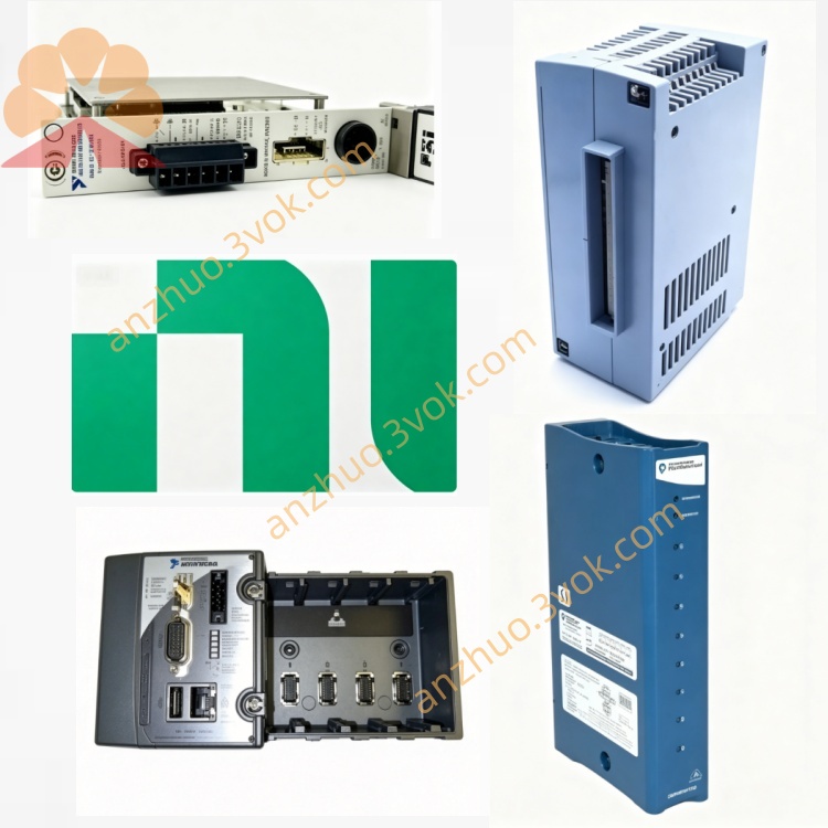
NI PXI‑4461 2‑Input 2‑Output 24‑Bit Sound‑Vibration DSA Module
Description
II. Model Interpretation
PXI: 3U PXI standard bus, single slot, compatible with PXI/PXIe mixed chassis.
4461: NI Dynamic Signal Acquisition (DSA) series code, representing 2 input 2 output, 24-bit, high dynamic range, IEPE, audio/vibration dedicated.
779687‑01: Standard model, including 2 analog inputs + 2 analog outputs + IEPE conditioning.
Location: Mid-to-high-end audio/vibration DSA, integrated excitation and acquisition, suitable for closed-loop testing, frequency response, noise vibration analysis.
III. Technical Parameters (25 ℃, preheating 30 min)
(1) Channel Configuration
ChannelTypeResolutionSampling / Update RateDynamic Range
AI0~AI1Analog Input (differential)24-bit Σ‑Δ ADCUp to 204.8 kS/s118 dB
AO0~AO1Analog Output (differential)24-bit Σ‑Δ DACUp to 204.8 kS/s118 dB
(2) Input Characteristics (AI)
Voltage Range: ±316 mV, ±1 V, ±3.16 V, ±10 V, ±31.6 V, ±42.4 V (6 levels).
Gain: -20, -10, 0, +10, +20, +30 dB (software selectable).
Coupling: AC/DC (per channel independently).
IEPE Conditioning: 0/4/10 mA constant current excitation, 24 V compliance, supports accelerometers/microphones.
Input Resistance: 1 MΩ || 240 pF (IEPE on); 100 kΩ (voltage mode).
No Aliasing Bandwidth: 92 kHz (204.8 kS/s).
THD+N: ≤‑100 dB (1 kHz, full scale).
(3) Output Characteristics (AO)
Voltage Range: ±1 V, ±3.16 V, ±10 V (4 levels).
Update Rate: 1 kS/s~204.8 kS/s (synchronous).
Output Resistance: 50 Ω (pseudo-differential).
No Mirror Bandwidth: 92 kHz.
THD+N: ≤‑95 dB (1 kHz, full scale).
(4) Electrical / Mechanical / Environmental
Power Supply: PXI backplane + 5 V/+12 V, maximum 12 W.
Connectors: 4×BNC (AI0/AI1/AO0/AO1).
Size / Weight: 3U single slot (216×20×130 mm); approximately 310 g.
Safety: IEC 61010‑1, CAT I 30 V.
Temperature: Operating 0 ℃~55 ℃; accuracy guaranteed 15 ℃~35 ℃.
Calibration Cycle: 1 year (NIST traceable).
IV. Interface and Communication Configuration
(1) Front-End I/O (BNC)
AI0/AI1: Differential analog input, supports IEPE/voltage input.
AO0/AO1: Differential analog output, used for excitation signal generation.
Trigger In/Out: PXI trigger synchronization, multi-module synchronous delay ≤ 1 μs.
(2) Status Indicator Lights (Panel)
PWR: Green = Normal power supply.
RUN: Green = Acquisition/output running; flashing = Trigger waiting.
ERR: Red = Fault (over-temperature / over-current / calibration error).
(3) Bus and Software
Bus: Standard PXI, compatible with PXIe, supports PXI Trigger/PFI synchronization. Driver: NI-DAQmx, compatible with LabVIEW/TestStand/Python/C#.
Configuration: NI MAX (identification, self-check, parameter configuration, calibration, triggering).
Software tools: Sound and Vibration Toolkit, Order Analysis Toolkit.
VII. Core Functions
2 Input 2 Output Synchronous Acquisition and Excitation: Closed-loop testing (such as vibration table control, speaker frequency response), synchronous delay < 1 μs.
118 dB Ultra High Dynamic Range: Simultaneous measurement of weak and strong signals, suitable for microphone/accelerometer wide range requirements.
Integrated IEPE Sensor Conditioning: 0/4/10 mA constant current, direct drive for IEPE accelerometers/microphones, simplifies wiring.
24-bit High Precision Σ-Δ Conversion: Low noise, low distortion, suitable for audio, vibration, acoustic precision testing.
Programmable Anti-aliasing / Anti-Reflection Filtering: Independent per channel, suppresses high-frequency interference, ensures measurement accuracy.
AC/DC Coupling + 6 Gain Levels: Suitable for DC (such as sensor bias) and AC (such as audio/vibration) signals.
Multi-module Synchronization: Up to 17 modules synchronized in a single chassis, supports multi-channel NVH/acoustic array testing.
TEDS Sensor Plug-and-Play: Automatically reads sensor electronic data sheet, automatically configures sensitivity/calibration.
VIII. Application Scenarios
Audio Testing: Speaker/earphone frequency response, distortion, signal-to-noise ratio; microphone calibration and sensitivity testing.
Automotive NVH: Vehicle/vehicle component noise, vibration, sound vibration roughness analysis; engine/transmission vibration monitoring.
Vibration and Structural Testing: Modal analysis, impact response, resonance point identification; rotating machinery condition monitoring (bearing/gear faults).
Acoustic Measurement: Environmental noise, sound pressure level, sound power; building/material sound insulation/acoustic testing.
Industrial Automation: Equipment health monitoring, fault diagnosis, predictive maintenance; production line vibration/noise quality control.
Research and Education: Precise measurement in acoustic/vibration laboratories; university dynamic signal analysis teaching experiments.
IX. Usage and Maintenance Instructions
(1) Installation and Power On
Installation: Disconnect power, insert PXI single slot, tighten panel screws; chassis properly grounded.
Preheating: Power on for 30 minutes to ensure 24-bit accuracy; NI MAX self-checks without errors.
Heat Dissipation: Normal fan operation, environmental temperature ≤ 55 ℃, no obstruction to ventilation openings.
(2) Wiring and Operation
BNC Wiring: Use 50 Ω coaxial cable for AI/AO, single-ended grounding of the shield layer to reduce interference.
IEPE Sensor: Enable IEPE (4 mA commonly used) for AI channels; do not connect ordinary voltage signals.
Coupling Selection: Use AC coupling for AC signals (audio/vibration); use DC coupling for DC/low-frequency signals.
Gain Setting: Signal amplitude close to full scale (≥ 80%), maximizes signal-to-noise ratio.
Synchronous Trigger: Use PXI Trigger for multi-module testing to ensure time synchronization.
(3) Maintenance and Calibration
Regular Calibration: Once per year external NIST traceable calibration; daily internal self-calibration to compensate for temperature drift.
Cleaning and Maintenance: Regularly clean BNC terminals of dust, keep dry; disconnect power for long-term storage to prevent dust, cover terminals for protection.
Environmental Control: Working environment 0 ℃~55 ℃, no condensation, humidity 5%~95% RH, away from strong vibration/strong electromagnetic interference.
Prohibition of Use: Do not allow overpressure (> ± 50 V) input; Avoid electrostatically charged BNC connections; the IEPE channel must not be connected to devices with high sensitivity to static electricity.
Get a Quote