
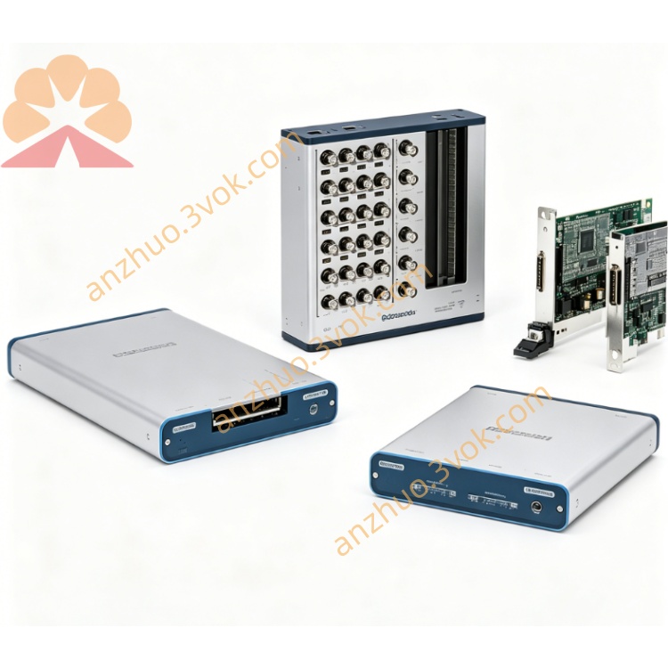
NI PXI‑4130 ±20 V 40‑W Isolated Dual‑Channel PXI SMU Module
Description
II. Model Interpretation
PXI: 3U PXI standard bus, single slot, compatible with PXI/PXIe mixed chassis.
4130: NI PXI SMU series code, representing four-quadrant, ±20 V/±2 A, isolated, nA level accuracy NI.
779647‑30: Standard version, without auxiliary power supply, CH1 power limited (source ≤ 10 W, sink ≤ 5 W).
779647‑31: High configuration version, includes APS‑4100 auxiliary power supply, CH1 full power (source 40 W, sink 10 W).
III. Technical Parameters (23 ℃ ± 5 ℃, preheating 30 min, with APS‑4100)
(1) Channel Configuration
ChannelTypeVoltage RangeCurrent RangePowerIsolation
CH0 (Utility)Single quadrant source0~+6 V±1 A6 WNon-isolated (PXI ground)
CH1 (SMU)Quadrant source / Sink±6 V / ±20 V±2 A (5 levels: 200 μA~2 A)Source 40 W / Sink 10 W±60 VDC (Channel - ground)
5% overload range: CH1 can enable 5% voltage / current overload (requires auxiliary power supply) NI.
(2) Programmable Control and Measurement Accuracy (16 bits)
Voltage (CH1)
Resolution: ±20 V level 0.4 mV; ±6 V level 0.12 mV NI.
Accuracy: 0.02% reading + 2 mV (20 V) NI.
Current (CH1, 5 levels)
Resolution: 1 nA (200 μA level) ~ 10 μA (2 A level) NI.
Accuracy: 0.05% reading + 10 nA (200 μA level) NI.
CH0 accuracy: Voltage 0.05% + 1 mV; Current 0.15% + 4 mANI.
Readback rate: Up to 3 kS/s (Voltage / Current synchronous) NI.
4-wire remote sensing: CH1 supports Kelvin measurement, eliminating lead resistance error.
(3) Dynamic and Protection
Ripple noise: ≤ 5 mVpp (20 MHz bandwidth) NI.
Rise time: ≤ 500 μs (10%~90%) NI.
Load regulation rate: ≤ 0.01% (full load change) NI.
Protection mechanism: Overvoltage, overcurrent, overheat, reverse polarity, hardware + software dual protection NI.
(4) Electrical / Mechanical / Environmental
Power supply: PXI backplane + APS‑4100 (12 V/3 A auxiliary power supply).
Power consumption: Internal approximately 12 W; External full load approximately 50 W.
Connector: Mini‑Combicon terminals (CH0/CH1/Sense/Isolated GND / Shield).
Size / Weight: 3U single slot (216×20×130 mm); approximately 380 g.
Safety: IEC 61010‑1, CAT I 60 V.
Temperature: Operating 0 ℃~55 ℃; Accuracy guaranteed 15 ℃~35 ℃.
Calibration cycle: 1 year (NIST traceable).
IV. Interface and Communication Configuration
(1) Front-end I/O (Mini‑Combicon)
CH0: +6 V non-isolated output.
CH1 (SMU): ±20 V isolated output.
Sense+ / Sense‑: CH1 4-wire remote sensing end.
Isolated GND: CH1 isolated ground. Shield: Shielded ground (optional with chassis ground).
(II) Status indicator lights (panel)
CH0/CH1 status: Off = Disabled; Green = Constant Voltage (CV); Amber = Constant Current (CC); Red = Fault (over-temperature / over-current).
Remote Sense: Off = Local; Green = Remote sensing enabled.
Aux Power: Off = No connection / Abnormal; Green = Normal.
(III) Bus and software
Bus: Standard PXI, compatible with PXIe, supports PXI Trigger synchronization with NI.
Driver: NI-DCPower (IVI), supports LabVIEW/TestStand/Python/C#NI.
Configuration: NI MAX (Identification, Self-check, Parameter Configuration, Calibration, Trigger Settings) NI.
Synchronization: PXI Trigger/PFI, multi-module synchronization delay ≤ 1 μs NI.
VII. Core functions
Four-quadrant bidirectional power (CH1): I/III quadrant power supply (source), II/IV quadrant power absorption (sink), replacing power supply + electronic load.
nA level ultra-high precision measurement: Minimum 1 nA resolution, suitable for leakage current, weak signal testing NI.
±60 V isolated output: CH1 isolated from system ground, avoiding ground loop, suitable for floating ground / high-voltage testing.
4-wire Kelvin measurement: Eliminate lead resistance error, necessary for precise resistance / component testing.
CV/CC automatic switching: Seamless switching between constant voltage / constant current modes, protecting DUT and instrument.
Channel cascading expansion: Multiple modules connected in series to ±40 V (3 ±60 V limit), parallel to 4 A, flexible expansion of power NI.
Built-in DMM readback: Synchronous precise measurement of voltage / current, no need for additional instruments NI.
Efficient integration: Single slot replaces SMU + power supply + load, saving cabinet space and cost.
VI. Application scenarios
Semiconductor device testing: MOSFET/IGBT/ diode IV curves, leakage current, breakdown voltage testing.
Battery / supercapacitor testing: Charge-discharge cycles, capacity / internal resistance testing (four-quadrant absorbing charging energy).
Power / voltage regulator testing: Load regulation rate, transient response, short-circuit protection verification.
Precise active load: Simulate various load characteristics, absorb power and precisely measure.
Sensor / optoelectronic device testing: Photovoltaic cells, photodiodes' weak current / voltage testing.
ATE mass production testing: High-precision parameter testing for automotive electronics, consumer electronics.
VII. Usage and maintenance instructions
(I) Installation and power-on
Installation: Power off, insert PXI single slot, tighten panel screws; high-end version connects to APS-4100 auxiliary power supply.
Preheating: Power on for 30 minutes to ensure accuracy; NI MAX confirms equipment is normal, self-check without errors NI.
Heat dissipation: Ensure fan of the cabinet is normal, environmental temperature ≤ 55 ℃, avoid blocking ventilation ports.
(II) Wiring and operation
Isolated channel wiring: CH1 must be connected to Isolated GND to avoid mixed connection with system ground causing ground loop.
4-wire remote sensing: For long-distance or low-resistance testing, be sure to connect Sense+ / Sense‑ to eliminate lead error.
Current limit: Set reasonable current upper limit according to the load to prevent overcurrent damage to DUT.
Cascading expansion: When connected in series, control single module to ≤ ±60 V relative to ground; when connected in parallel, ensure voltage consistency and good current distribution NI.
High-voltage operation: Pay attention to insulation when ±20 V output, avoid short circuit; The isolation channel must not be operated directly grounded.
(III) Maintenance and Calibration
Regular calibration: Conduct an external NIST traceable calibration once a year; perform daily internal self-calibration to compensate for temperature drift.
Cleaning and maintenance: Regularly clean the dust on the terminal connections to keep them dry; disconnect power and cover with a dust shield when the equipment is idle for a long time.
Environmental control: The working environment should be between 0 ℃ and 55 ℃, without condensation, and away from strong vibration / strong electromagnetic interference.
Prohibition of use: Do not use with excessive pressure / flow; avoid frequent short-circuit impacts; the isolation channel must not be operated with grounding.
Get a Quote