
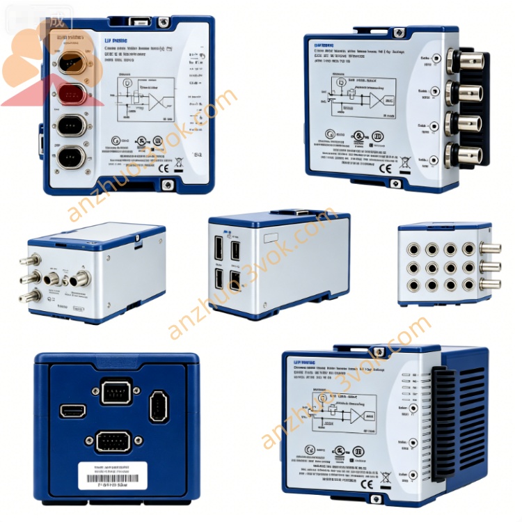
NI PXI‑2531 512‑Crosspoint Reed‑Relay Matrix Switch Module
Description
II. Model Interpretation
PXI: PCI eXtensions for Instrumentation, standard PXI bus interface, compatible with PXI chassis.
2531: NI 2500 series switch module, representing 512 cross points, single-line matrix, reed relays specifications.
Part Number: 778572-31.
Product Status: Out of Production (EOL), replacement model is PXIe-2531.
III. Technical Parameters
1. Channels and Topology
Total Cross Points: 512 (single line).
Matrix Topology: 4×128, 8×64, dual 4×64, dual 8×32 (all single line).
Relay Type: Compact reed relays, high-speed, high stability.
Maximum Drive Limit: 40 relays.
2. Electrical Characteristics
Maximum Switching Voltage: 60 VDC / 30 VAC (rms), CAT I/0 category.
Maximum Switching Current: 0.5 A / channel.
Maximum Switching Power: 30 W (DC), 15 VA (AC).
On-Resistance: Typical ≤ 150 mΩ.
Bandwidth: DC to 10 MHz (-3 dB).
Isolation (50Ω Terminal): 1 MHz > 51 dB, 10 MHz > 32 dB.
Relay Lifespan: Typical 10^8 times under resistive load.
3. Dynamic Performance
Switching Time: < 1 ms (typical).
Maximum Scanning Rate: 2000 cycles / second.
Scanning List: Supports long sequence deterministic scanning.
4. Physical and Environmental
Form: 3U PXI single-slot (21.6 cm × 2.0 cm × 13.0 cm).
Weight: Approximately 260 g.
Operating Temperature: 0–55 ℃; Storage: -40–70 ℃.
Humidity: 5%–85% RH (no condensation).
Power Consumption: Approximately 4.5 W with 5V supply.
IV. Interface and Communication Configuration
Bus Interface: Standard PXI mixed bus, supports hot plugging, plug-and-play.
Signal Interface: 2 front panel VHDCI high-density female connectors, compatible with single-line matrix topology wiring.
Trigger and Synchronization: PXI trigger lines (0–7), supports hardware triggering, multi-module synchronous scanning and timing linkage.
Software Driver: Companion NI-SWITCH driver, compatible with LabVIEW, TestStand, LabWindows/CVI, supports C/C++/Python API and IVI standard driver.
V. Core Functions
Ultra-high Density Matrix Routing: 512 cross points, supports various single-line topologies such as 4×128/8×64, single module realizes large-scale signal distribution.
High-Speed Low-Latency Switching: Reed relays operate in sub-millisecond level, 2000 cycles / second scanning rate, suitable for high-speed test sequences.
High Bandwidth and High Isolation: 10 MHz bandwidth, excellent isolation at high frequencies, suitable for medium and high-frequency signal routing.
Onboard Relay Counting: Built-in action count statistics, supports predictive maintenance, early warning of aging relays.
Deterministic Synchronous Scanning: Hardware-triggered synchronization, ensures consistency of measurement timing for multi-modules and multi-channels.
VI. Application Scenarios
Semiconductor High-Density Testing: Multi-channel parameter testing, functional verification and signal routing of chips, wafers, components.
Large-scale Automated ATE: Batch production testing and aging screening of consumer electronics, communication equipment, circuit boards.
High-Speed Data Acquisition System: High-speed scanning and acquisition of multi-channel sensors, low-voltage signals.
Signal Distribution and Switching: Laboratory multi-instrument signal switching, multi-channel parallel testing system setup.
Low current precision testing: Suitable for high-speed switching and measurement of low-voltage and small current signals.
VII. Usage and Maintenance Instructions
1. Installation and Wiring
The module must be unplugged when the power is off. After inserting it into the PXI slot, tighten the fixing screws.
Use VHDCI interface cables to connect the signals. Strictly control the input to be no more than 60 V and 0.5 A, and only for CAT I/0 circuits.
The chassis and the tested equipment should be reliably grounded to reduce electromagnetic interference and electrostatic damage.
The bimetal relay module should be away from strong magnetic field areas to avoid magnetic field interference causing the relay to act.
2. Software Configuration
Install the NI-SWITCH driver, identify the module through NI-MAX and configure the matrix topology.
Based on LabVIEW or text language programming, implement channel switching, automatic scanning, synchronous measurement and other functions.
Configure multi-module synchronization using the hardware trigger function to improve the timing accuracy of the testing system.
3. Daily Maintenance
After regular power-off, use a dust-free soft cloth to clean the panel and interfaces to prevent dust and liquids from entering the ports.
Maintain the working environment at 0–55 ℃ without condensation, and avoid strong electromagnetic interference and strong magnetic field areas.
Avoid connecting inductive loads. If connecting inductive components, a surge protection circuit must be added.
When plugging or unplugging the module or wiring, wear an anti-static wrist strap to prevent static electricity from breaking the internal circuits.
Get a Quote