
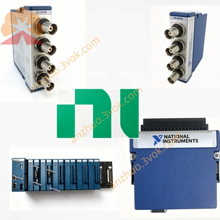
NI PXI‑4060 5½‑Digit PXI Digital Multimeter Module
Description
II. Model Interpretation
PXI: Compliant with the PXI bus specification, 3U size, single-slot installation.
4060: The serial number of the NI DMM series, representing 5½ digit resolution, basic accuracy, medium-high speed sampling.
Full name: PXI-4060 5½ digit multi-function digital multimeter module.
Position: General-purpose PXI DMM, replacing traditional bench multimeters, suitable for integration in automated test systems.
III. Technical Parameters
(1) Measurement Functions and Ranges (25℃ ± 1℃)
DC Voltage (DCV)
Range: 100 mV / 1 V / 10 V / 100 V / 300 V
24-hour accuracy: 0.006% reading + 7 μV (2 V range) docs-be.ni.com
Temperature coefficient: 0.0005%/℃ + 0.5 μV/℃
AC Voltage (True RMS ACV)
Range: 100 mV / 1 V / 10 V / 100 V / 300 V
Bandwidth: 10 Hz~100 kHz
Accuracy: 0.02% reading + 50 μV (1 V range, 1 kHz)
DC Current (DCI)
Range: 100 μA / 1 mA / 10 mA / 100 mA / 200 mA
Accuracy: 0.01% reading + 50 nA (10 mA range)
AC Current (True RMS ACI)
Range: 100 μA / 1 mA / 10 mA / 100 mA / 200 mA
Bandwidth: 10 Hz~100 kHz
Accuracy: 0.05% reading + 500 nA (10 mA range, 1 kHz)
Resistance (Ω)
Mode: 2-wire / 4-wire
Range: 10 Ω / 100 Ω / 1 kΩ / 10 kΩ / 100 kΩ / 1 MΩ / 10 MΩ / 200 MΩ
Accuracy: 0.01% reading + 10 mΩ (1 kΩ range, 4-wire)
Resolution: Software selectable 5½ digit (up to 18 bit) / 4½ digit / 3½ digit
Reading rate: Up to 60 times/second (3½ digit); approximately 10 times/second for 5½ digit
(2) Electrical and Physical Characteristics
Power Supply: PXI backplane + 5 V; typical 250 mA, maximum 300 mAdocs-be.ni.com
Connectors: Front-end 4 safety banana jacks (VΩ, I, LO, ground)
Size: 3U PXI single slot, 10 mm × 160 mm × 216 mm docs-be.ni.com
Weight: Approximately 0.4 kg
Safety level: Compliant with IEC 61010-1, UL 61010-1, CSA 61010-1 docs-be.ni.com
(3) Environmental Parameters
Operating temperature: 0 ℃~55 ℃ (accuracy guaranteed at 15 ℃~35 ℃) docs-be.ni.com
Storage temperature: –20 ℃~70 ℃ docs-be.ni.com
Humidity: 10%~90%, no condensation docs-be.ni.com
Preheating time: 30 minutes (to ensure accuracy)
IV. Interface and Communication Configuration
(1) Front-end I/O Interface
4 × safety banana sockets (UL 3111/IEC 1010-1 certified)
VΩ: Voltage / resistance measurement positive terminal
I: Current measurement positive terminal LO: Common negative terminal (shared for all measurements)
Ground: Shielded ground to reduce noise interference
Adapter probe: Standard safety banana plug test cable, supporting third-party probes that meet safety standards
(II) Bus and Software Communication
Bus interface: Standard PXI bus, compatible with PXI/PXIe chassis mixed slots
Driver: NI-DMM (compliant with IVI specification, compatible with LabVIEW/TestStand)
Software support: LabVIEW, TestStand, LabWindows/CVI, Python, C/C++, .NET
Configuration tool: NI MAX (hardware identification, calibration, channel configuration, trigger settings)
Trigger function: Supports **PFI (Programmable Function Input)** trigger, multi-module synchronous measurement by NI
Calibration: Supports internal self-calibration and external calibration (requires standard source)
VII. Core Functions
5½ digit high-precision measurement: DC voltage accuracy up to ppm level, suitable for precise power supplies, sensors, semiconductor device testing.
5-in-1 multi-function: Covers DCV/ACV/DCI/ACI/resistance, one unit replaces multiple bench instruments, simplifies the system.
True RMS AC measurement: Precisely measures non-sinusoidal waveforms (such as frequency converters, switch power supply output), avoiding average value error.
4-wire resistance measurement: Eliminates lead resistance influence, suitable for **low-resistance precise resistors, RTD (platinum resistors)** measurement.
Programmable resolution and rate: 5½ digit (high precision)/4½ digit (balanced)/3½ digit (high speed) adjustable, suitable for different testing requirements.
Multi-channel expansion capability: Combined with PXI-2501/2503 etc. multi-channel switch modules, can be expanded to thousands of channels to achieve batch testing.
Relay life monitoring: Board-mounted channel status recording, supports long-term stability tracking.
VI. Application Scenarios
Automated production testing: PCB boards, power modules, semiconductor discrete components, sensors' voltage/current/resistance batch testing.
Portable field measurement: Vehicle test systems, field equipment calibration, battery performance testing, industrial equipment maintenance.
Laboratory research and verification: Precise circuit debugging, device characteristic analysis, power ripple testing, sensor calibration.
Data acquisition and monitoring: Thermocouples (requiring compensation), RTD, 4-20 mA current loop signal acquisition, environmental and equipment status monitoring.
Education and research: University laboratory teaching, basic electrical parameter measurement in research projects, low-cost high-precision solution.
VII. Usage and Maintenance Instructions
(I) Installation and Power On
Before installation, turn off the power, insert the module into a single slot of the PXI chassis, tighten the panel screws for fixation.
After power-on, preheat for 30 minutes to ensure measurement accuracy (reducing temperature drift influence).
Confirm in NI MAX that the device identification is normal and there are no errors, complete driver installation and self-check.
(II) Wiring and Operation
Caution for high voltage / large current: When measuring ≥100 V or ≥100 mA, use a safety banana plug to avoid electric shock.
4-wire resistance wiring: I+ / I- (current wires) and V+ / V- (voltage wires) are connected separately to eliminate lead resistance error.
Range selection: Prefer automatic range; when using manual range, start from the largest range to avoid over-range damage.
Trigger settings: When multi-module is synchronous, configure through PFI trigger line to ensure consistent measurement timing by NI.
(III) Maintenance and Calibration
Regular calibration: It is recommended to calibrate once a year or calibrate when accuracy drifts. Use NIST traceable standard source.
Cleaning and maintenance: Use a soft-bristled brush to remove dust, avoid contact with liquids; Keep the interface dry and cover it with a dust cap when not in use for a long time.
Environmental control: The working temperature should be controlled within 0 ℃ to 55 ℃. Avoid high temperature and high humidity to extend the module's lifespan.
Avoid overloading: Do not exceed the range (such as input of 300 V range > 300 V) to prevent internal circuit damage.
Get a Quote