
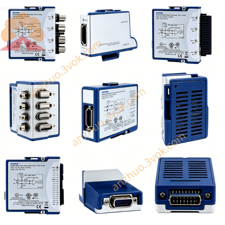
NI PXI‑4070 6½‑Digit ±300 V FlexDMM with 1.8 MS/s Isolated Digitizer Module
Description
II. Model Interpretation
PXI: 3U PXI standard bus, single slot, compatible with PXI/PXIe mixed chassis.
4070: The serial number of the NI FlexDMM series, representing a 6½-digit, 300V, 1.8MS/s digital instrument.
Full name: PXI-4070 6½-digit FlexDMM (with isolated digital instrument).
Positioning: A combination of precise DMM and high-speed acquisition card, replacing the traditional "DMM + oscilloscope" configuration, saving slots and costs.
III. Technical Parameters (25℃ ± 1℃, calibration cycle 2 years, preheating 1 hour)
(1) DMM Mode Measurement Function
DC Voltage (DCV)
Range: 100 mV / 1 V / 10 V / 100 V / 300 V
2-year accuracy: 25 ppm reading + 5 ppm (10V range)
Temperature coefficient: 0.5 ppm/℃ + 0.1 μV/℃
AC Voltage (True RMS ACV)
Range: 50 mV / 500 mV / 5 V / 50 V / 300 V
Bandwidth: 10 Hz~100 kHz
Accuracy: 0.02% reading + 50 μV (5V range, 1kHz)
DC Current (DCI)
Range: 20 mA / 200 mA / 1 A
Accuracy: 0.05% reading + 50 nA (200 mA range)
AC Current (True RMS ACI)
Range: 20 mA / 200 mA / 1 A
Bandwidth: 10 Hz~100 kHz
Accuracy: 0.1% reading + 500 nA (200 mA range, 1kHz)
Resistance (Ω)
Mode: 2-wire / 4-wire
Range: 10 Ω~100 MΩ (2-wire); 10 Ω~1 MΩ (4-wire)
Accuracy: 0.02% reading + 10 mΩ (1 kΩ range, 4-wire)
Frequency / Period: 10 Hz~100 kHz, accuracy 0.01%
Diode Testing: 3.5 V@1 mA
Resolution: 6½-digit (maximum 23 bit), software can be reduced to 5½/4½-digit
Reading Rate: DMM mode maximum 100 times/second (6½-digit); 3½-digit up to 3,000 times/second
(2) Digital Instrument Mode (Core Advantages)
Sampling Rate: Maximum 1.8 MS/s (single channel)
Resolution: 10~23 bit adjustable (adapted dynamically to sampling rate)
Input Range: ±10 V / ±100 V / ±300 V (isolated)
Bandwidth: DC~500 kHz
Isolation Voltage: 300 Vrms (channel - ground isolation)
Trigger: Edge / Window / Pulse Width / Digital Trigger, delay as low as 2 μs
(3) Electrical and Physical Characteristics
Power Supply: PXI backplane + 5 V; typical 400 mA, maximum 500 mA
Connectors: Front-end 4 safety banana sockets (VΩ, I, LO, ground) + 1 9-pin DIN trigger / auxiliary I/O port NI
Size: 3U PXI single slot, 10 mm × 160 mm × 216 mm
Weight: Approximately 0.57 kg NI
Safety Level: IEC 61010-1, UL 61010-1, CSA 61010-1 (CAT II)
(4) Environmental Parameters Operating temperature: 0 ℃ to 40 ℃ (accuracy guaranteed within 15 ℃ to 35 ℃) NI
Storage temperature: -40 ℃ to 70 ℃ NI
Humidity: 10% to 90% (operation), 5% to 95% (storage), no condensation
Preheating time: 1 hour (ensuring 6½ digit accuracy) NI
Calibration period: 2 years (NIST traceable) NI
IV. Interface and Communication Configuration
(1) Front-end I/O Interface
4 × Safety banana sockets (gold-plated low-thermal-electric-copper material, low-leakage insulation) NI
VΩ: Voltage / Resistance positive terminal
I: Current positive terminal (built-in 1.5 A fast fuse)
LO: Common negative terminal
Ground: Shielded ground (isolated from the digital instrument ground)
9-pin DIN interface (AUX I/O): Trigger input/output, PXI Trigger synchronization, SCXI communication NI
(2) Bus and Software Communication
Bus interface: Standard PXI bus, compatible with PXI/PXIe mixed slots
Driver: NI-DMM (IVI compliant) + NI-Digitizer
Software support: LabVIEW, TestStand, LabWindows/CVI, Python, C/C++, .NET
Configuration tool: NI MAX (hardware identification, self-calibration, trigger configuration, channel testing)
Trigger function: PXI Trigger, PFI, software trigger; multi-module synchronization, delay ≤ 2 μs
Calibration: Internal self-calibration (real-time compensation for temperature drift) + external calibration (2-year cycle)
VII. Core Functions
6½-digit high-precision DMM: DC voltage accuracy up to ppm level, suitable for precise power supplies, sensors, semiconductor device testing.
1.8 MS/s isolation digitalizer: High-speed waveform capture, measurement of transient voltage/current, power ripple, switching noise, replacing independent oscilloscope NI.
300 V isolation measurement: Channel - ground isolation 300 Vrms, safe measurement of high-voltage floating ground signals, protecting system and personnel NI.
Flexible resolution (10 to 23 bits): Sampling rate and resolution dynamically balanced,兼顾 high speed and high precision.
True RMS AC measurement: Precise measurement of non-sinusoidal waveforms (variable frequency converter, switch power supply output), no average value error.
4-wire resistance measurement: Eliminate lead resistance, suitable for ** low-resistance precise resistors, RTD (platinum resistors)** measurement.
Multi-instrument integration: DMM + digitalizer, single slot replacement of "multimeter + oscilloscope + data acquisition card", simplifying system, reducing cost NI.
Built-in self-calibration: Real-time compensation for temperature drift and long-term drift, maintaining accuracy in the full temperature range (0 to 55 ℃).
VI. Application Scenarios
Power module testing: High-precision DC/AC parameters + waveform capture of ripple / transient, suitable for switching power supplies, lithium battery management systems.
Semiconductor device testing: Static parameters of diodes, MOSFETs, IGBTs + dynamic switching waveform measurement.
Precise sensor calibration: High-precision resistance / voltage measurement of RTD, thermocouple, pressure sensor + dynamic response waveform acquisition.
Automated test system (ATE): Batch precise testing of PCB, medical equipment, communication modules, balancing static parameters and dynamic waveforms.
Laboratory research and verification: Precise circuit debugging, power stability analysis, transient signal capture, device characteristic characterization.
Industrial equipment maintenance: On-site precise measurement of high-voltage equipment, motors, frequency converters + waveform diagnosis.
VII. Usage and Maintenance Instructions
(1) Installation and Power On Before installation, turn off the power supply. Insert the PXI chassis into a single slot and tighten the screws on the panel.
After powering on, let it preheat for 1 hour to ensure 6½-digit accuracy (reducing temperature drift) from NI.
In NI MAX, confirm that the equipment is normal and there are no errors, and complete the driver installation and self-check.
(II) Wiring and Operation
High-voltage safety: When measuring ≥ 100 V, use a safety banana plug to avoid electric shock; do not exceed 300 V input.
4-wire resistance connection: Connect I+ and I‑ (current wires) and V+ and V‑ (voltage wires) separately to eliminate lead errors.
Digital instrument mode: When measuring high-voltage floating ground signals, use isolated ground (LO / ground) to avoid common ground interference.
Fuse replacement: When the current range is overloaded, replace the 1.5 A fast fuse after power off.
(III) Maintenance and Calibration
Regular calibration: Calibrate once every 2 years using a NIST traceable standard source; internal self-calibration can compensate for temperature drift in real time.
Cleaning and maintenance: Use a dry cloth or soft brush to remove dust, keep the interface dry, and cover with a dust cap when not in use for a long time.
Environmental control: Working temperature is 0 ℃ to 40 ℃; avoid high temperature and high humidity to extend module lifespan.
Avoid overload: Do not exceed the range (such as input > 300 V in the 300 V range) to prevent internal circuit damage.
Get a Quote