
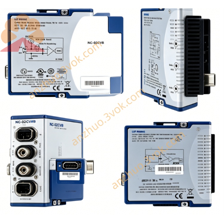
NI PXI‑4071 (778271‑01) 7‑Digit High‑Precision Isolated FlexDMM Module
Description
II. Model Interpretation
PXI: Compliant with the standard PXI bus specification, 3U single-slot structure, compatible with both PXI and PXIe mixed chassis peripheral slots.
4071: The code for the high-end series of NI FlexDMM, representing 7½-bit resolution, 1000 V high-voltage range, and integrated high-speed isolation digital instrument.
778271-01: The original factory component number for the module, used for procurement, spare parts, and model verification.
Full name: PXI-4071 7½-bit FlexDMM high-voltage isolation multi-function universal meter module (component number 778271-01).
Product positioning: An industrial-grade / measurement-grade dual-purpose instrument, replacing traditional desktop 7½-bit digital multimeter + independent high-voltage digital instrument / oscilloscope, saving cabinet slots, and compatible with automated test system integration.
III. Technical Parameters
(1) General reference conditions
Environment: 25 ℃ ± 1 ℃; Calibration cycle: 2 years; Preheating time for full load accuracy: 1 hour.
(2) DMM measurement functions and indicators
Direct Current Voltage (DCV)
Range: 100 mV, 1 V, 10 V, 100 V, 1000 V
2-year accuracy: 7 ppm reading + 0.5 ppm (10 V range)
Temperature coefficient: 0.1 ppm/℃ + 0.01 μV/℃
True RMS AC Voltage (ACV)
Range: 100 mV, 1 V, 10 V, 100 V, 1000 V
Working bandwidth: 10 Hz ~ 100 kHz
Accuracy: 0.01% reading + 20 μV (10 V @ 1 kHz)
Direct Current Current (DCI)
Range: 10 mA, 100 mA, 1 A, 3 A
Accuracy: 0.02% reading + 10 nA (1 A range)
True RMS AC Current (ACI)
Range: 10 mA, 100 mA, 1 A, 3 A
Working bandwidth: 10 Hz ~ 100 kHz
Accuracy: 0.05% reading + 100 nA (1 A @ 1 kHz)
Resistance measurement
Supports 2-wire / 4-wire Kelvin measurement
2-wire range: 100 Ω ~ 5 GΩ
4-wire range: 100 Ω ~ 1 MΩ
4-wire accuracy: 0.005% reading + 5 mΩ (1 kΩ range)
Frequency / Period
Measurement range: 10 Hz ~ 100 kHz
Accuracy: 0.005%
Diode testing
Testing conditions: 3.5 V @ 1 mA
Resolution and reading rate
Highest resolution: 7½-bit (26 bit), software can be downgraded to 6½/5½/4½-bit
Reading rate: 7½-bit approximately 7 times/second; 6½-bit up to 100 times/second; 3½-bit up to 3000 times/second
(3) Isolation Digital Instrument Mode
Highest sampling rate: 1.8 MS/s (single channel)
Sampling resolution: 10 ~ 26 bit adjustable dynamically
Input range: ±10 V, ±100 V, ±1000 V
Analog bandwidth: DC ~ 500 kHz
Channel-to-ground isolation voltage: 1000 Vrms
Trigger type: edge trigger, window trigger, pulse width trigger, digital trigger
Trigger delay: as low as 2 μs
(4) Electrical, physical and environmental parameters
Power supply and power consumption
Derived from the PXI backplane 3.3 V/5 V/12 V; typical total power consumption 6.9 W, maximum 8 W.
Mechanical specifications Appearance: Standard 3U PXI single-slot module
Dimensions: 216 mm × 20 mm × 130 mm
Weight: Approximately 314 g
Safety level
Complies with IEC 61010-1, UL 61010-1, CSA 61010-1, and CAT III safety level. Environmental parameters
Operating temperature: 0 ℃ ~ 40 ℃ (accuracy guaranteed range: 15 ℃ ~ 35 ℃)
Storage temperature: -40 ℃ ~ 70 ℃
Relative humidity: 10% ~ 90% in working state, 5% ~ 95% in storage state, no condensation throughout the process
IV. Interface and Communication Configuration
(1) Front-end I/O Interface
5 safety banana sockets (low thermoelectric potential, gold-plated material)
HI: Main positive terminal for voltage and resistance measurement
LO: Common reference negative terminal
HI Sense: Positive terminal for 4-wire resistance sensing
LO Sense: Negative terminal for 4-wire resistance sensing
Shielded ground: Isolation ground of the digital instrument, suppressing common-mode interference
9-pin circular DIN auxiliary interface
Integrated trigger input/output, PXI bus synchronization signal, SCXI expansion communication interface, used for multi-module timing synchronization.
(2) Bus and Software Communication
Bus Interface
Standard PXI backplane bus, compatible with PXI chassis, PXIe mixed slot, automatically acquires power, clock, trigger signal. Driver
Standard configuration: NI-DMM (compliant with IVI driving specification) + NI-Digitizer. The dual drivers correspond to the functions of multimeter and digitizer respectively.
Software package
Fully supports development environments such as LabVIEW, TestStand, LabWindows/CVI, Python, C/C++, and .NET.
Configuration and calibration tools
NI MAX: Hardware identification, device self-check, parameter configuration, trigger settings, internal self-calibration, status monitoring.
Synchronization and triggering
Supports PXI backplane Trigger bus and PFI programmable function input/output to achieve high-precision synchronization measurement of multiple modules.
VII. Core functions
7½ digit high-precision ultra-high accuracy
Equipped with an ultra-low drift reference source, with voltage measurement accuracy up to ppm level, meeting the requirements of metrological transfer and precise component calibration.
1000 V high-voltage measurement + isolation protection
Both the multimeter and digitizer support a 1000 V range, 1000 Vrms electrical isolation, safe measurement of high-voltage floating ground signals, protecting equipment and operators.
Multimeter + digitizer two-in-one
Simultaneously achieve static electrical parameter measurement and dynamic waveform acquisition, with a single module replacing multiple instruments, simplifying the test system architecture.
High-performance 4-wire Kelvin resistance measurement
Completely eliminate lead resistance error, suitable for testing high-precision resistance sensors such as precise low-resistance, RTD platinum resistors.
True RMS AC measurement
Precisely collect non-sinusoidal waveform signals, suitable for testing distorted waveforms of inverters, switching power supplies, and inverter equipment.
Flexible resolution and rate configuration
Resolution and sampling rate can be flexibly switched by software, balancing ultra-high precision, conventional precision, and high-speed acquisition for different conditions.
Internal and external dual calibration
Built-in real-time self-calibration function, automatically compensating for temperature drift; supports external traceability calibration to ensure long-term measurement accuracy.
Strong anti-interference design
Isolation circuit + shielding structure, suitable for long-term stable measurement in industrial complex electromagnetic environments.
VIII. Application scenarios
Metrology calibration laboratory
As a reference standard instrument, calibrate various digital multimeters, standard power supplies, measuring instruments.
High-voltage power supply and power electronics testing
Static parameter, ripple, transient waveform testing of 1000 V DC power supply, high-voltage inverter power supply, charging module.
Power semiconductor R&D and production testing
Static parameters, switching dynamic waveform characterization of IGBT, MOSFET, high-voltage diode, etc.
High-end precision sensor calibration
Laboratory calibration and dynamic response testing of high-precision RTD, thermocouples, pressure/position sensors.
Aerospace, military, medical electronic ATE system
High-reliability equipment batch testing, balancing precision, high-voltage, and waveform acquisition multiple requirements.
Industrial high-voltage equipment operation
On-site parameter detection and fault waveform diagnosis of high-voltage frequency converters, transformers, distribution cabinets, etc. The current terminals (HI/LO) and the sensing terminals (HI Sense/LO Sense) are separately wired and connected strictly in Kelvin connection method.
Digital instrument mode
When measuring high-voltage floating ground signals, the isolated ground terminals should be preferred to avoid common ground interference.
Current range protection
When the current circuit is overloaded, replace the same specification 3 A fast fuse fuse after power off, and prohibit using non-standard fuse tubes.
(III) Daily maintenance and calibration
Regular calibration
It is recommended to perform an external traceability calibration once every 2 years, combined with a NIST traceable standard source; daily rely on internal self-calibration to compensate for temperature drift.
Cleaning and maintenance
Regularly use a soft brush to clean the dust on the panel interfaces, and prohibit liquid contact with the module circuit; when the module is idle for a long time, install a dust cover on the interfaces.
Environmental control
The working environment should be maintained at 0 ℃ ~ 40 ℃, without condensation, and away from high temperature, high humidity, strong vibration, and strong electromagnetic radiation areas.
Usage prohibitions
Do not use beyond the range or beyond the isolation voltage; avoid frequent impact of large current input, to extend the module service life.
Get a Quote