
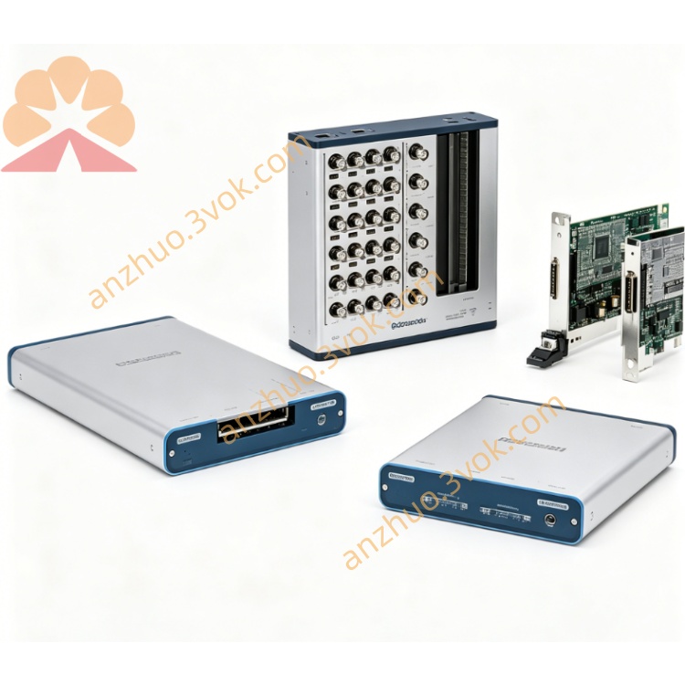
NI PXI‑2515 35‑Channel Reed‑Relay Signal‑Insertion Switch Module
Description
II. Model Interpretation
PXI: PCI eXtensions for Instrumentation, compatible with PXI/PXIe hybrid slots.
2515: 2500 series (fault insertion / signal switch), 15 represents 35 channels, high-speed 50 MHz, low-power digital signal type.
Part Number: 778572-15 (PXI); 780587-15 (PXIe-2515).
Status: In stock (NI's mainstream high-speed digital test dedicated FIU).
III. Technical Parameters
Channel Configuration:
Pass-through channels: 35 (32 independent signal channels + 3 dedicated channels)
Fault Bus: 2 (Bus A/B, programmable as ground, power supply, reference voltage)
Topology: Each channel supports "direct connection / disconnection / short circuit to Bus A/B" four states
Electrical Characteristics:
Maximum switching voltage: 30 VDC
Maximum switching current: 0.25 A (per channel)
Maximum carrying current: 0.3 A (per channel)
Conduction Resistance: <1.5 Ω (typical)
Relay Type: Reed Relay (Reed)
Protection: Overcurrent, overvoltage, ESD protection
Dynamic Performance:
Bandwidth: 50 MHz
Minimum pulse width: 150 ns
Channel skew: <130 ps (typical)
Switching Time: <1 μs (typical)
Relay Life: 10^8 times (typical, resistive load)
Physical and Environmental:
Size: 3U PXI (100 mm × 160 mm)
Weight: Approximately 0.25 kg
Operating Temperature: 0–55 °C; Storage: −40–70 °C
Humidity: 10%–90% RH (no condensation)
IV. Interface and Communication Configuration
Host Interface: PXI hybrid bus (compatible with PXIe/PXI), supports hot plugging, plug-and-play.
Signal Interface:
DUT Interface: VHDCI 68-pin (test device end)
HSDIO Interface: VHDCI 68-pin (connected to NI high-speed DIO device)
Fault Bus: 2×BNC (Bus A/B, front panel)
Trigger and Synchronization:
PXI Trigger Line: 70 ns resolution, supports multi-module synchronization
Hardware Trigger: Adapted for HIL real-time timing and high-speed digital testing
Driver Software: Compatible with NI-SWITCH 4.0+, NI-DAQmx 9.0+, LabVIEW Real-Time, NI VeriStand, TestStand, C/C++/Python API.
V. Core Functions
High-speed Digital Fault Injection: 50 MHz bandwidth, 150 ns minimum pulse, compatible with SPI, I²C, CAN/LIN, LVDS, etc. high-speed digital bus fault simulation.
High-density Channels and Flexible Topology: 35 independent channels + 2 fault buses, each channel can be independently configured as direct connection / open circuit / short circuit, achieving complex fault combinations.
Precise Timing and Low Skew: <130 ps channel skew, suitable for high-speed digital pin parameter testing and timing-sensitive scenarios.
Reed Relay High Reliability: 10^8 life, low conduction resistance, high-speed switching, suitable for long-term automated testing and high-density switching applications.
HIL and Parameter Testing Integration: Combined with NI high-speed DIO/SMU/DMM, realizes digital pin open circuit / short circuit / leakage / withstand voltage testing and HIL real-time fault injection.
VI. Application Scenarios High-speed digital bus testing: Fault injection and robustness verification for automotive CAN/LIN, industrial SPI/I²C, communication LVDS and other buses.
Chip/module pin testing: Open/closed circuit/leakage/voltage endurance parameter testing for digital pins of MCU, FPGA, SoC, and vehicle ECU.
HIL hardware-in-the-loop testing: Digital I/O fault simulation and real-time system verification for aviation/automotive electronic controllers.
Semiconductor and electronic manufacturing testing: High-speed digital function testing and fault screening for wafers/chips/wafer cards.
Embedded system reliability verification: Digital interface fault tolerance testing for industrial control, medical equipment, and consumer electronics.
VII. Installation and Maintenance Instructions
Installation and Wiring:
Module: Power off and plug/unplug, insert into PXI/PXIe mixed slot, tighten the fixing screws.
Wiring: Connect the VHDCI interface to the DUT and HSDIO device according to channel definition, connect the fault bus (ground/power) using BNC, strictly avoid exceeding 30 V and 0.25 A.
Grounding: Reliable connection between the chassis and system ground, independent grounding of the fault bus, reducing high-frequency interference.
Software Configuration:
Install NI-SWITCH and NI-DAQmx drivers, NI-MAX recognizes the module, configure the fault bus mapping.
Programming: Call the switch VI in LabVIEW, or configure the real-time fault sequence in VeriStand, conduct timing tests with high-speed DIO devices.
Daily Maintenance:
Cleaning: Use a soft cloth to wipe the panel after power off, avoid liquid entering the VHDCI/BNC interface.
Environment: Working temperature 0–55 °C, avoid dust, moisture, and strong electromagnetic interference.
Protection Mechanism: Avoid overpressure (>30 V), overcurrent (>0.25 A), inductive loads (without surge suppression), extend relay lifespan.
Static Protection: Wear an anti-static wristband when plugging/unplugging the module, ensure good grounding of the chassis.
Get a Quote