
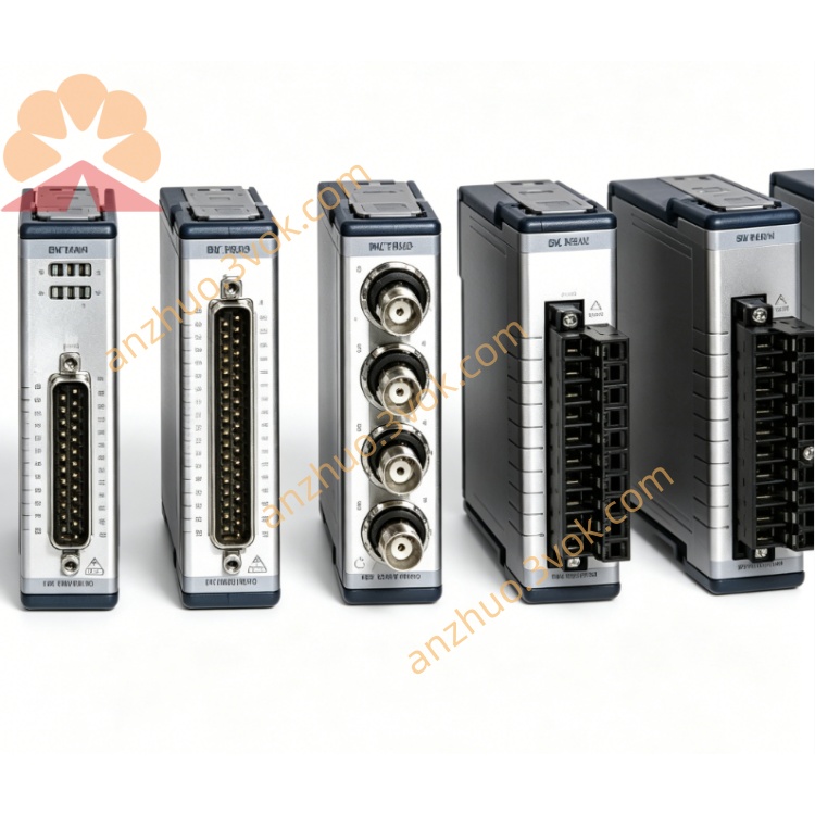
NI PXI‑2556 2.5‑GHz 75‑Ohm Dual SP4T RF Mux Module
Description
Model Explanation
PXI: PXI bus standard (PCI eXtensions for Instrumentation)
2556: Product serial number, specifically referring to the dual 4×1 75Ω RF multiplexer
Full name: PXI-2556 / 778572-56 → 2.5 GHz 75Ω Dual 4×1 Multiplexers (Dual SP4T)
Topological alias: NISWITCH_TOPOLOGY_2556_DUAL_4X1_MUXNI Technical Specifications
RF Performance
Bandwidth: DC~2.5 GHz
Characteristic Impedance: 75 Ω (suitable for video / CATV) NI
Terminal Matching: No built-in terminal (external matching)
Insertion Loss: ≤ 0.7 dB @ 2.5 GHz
VSWR: ≤ 1.4:1 @ 2.5 GHz
Channel Isolation: ≥ 55 dB @ 2.5 GHz
Switching and Electrical
Topology: Dual 4×1 (Dual SP4T), two independent groups A/B, each group 4 inputs 1 output NI
Relay Type: RF Pneumatic Relay (latching)
Maximum Switching Voltage: 30 V NI
Maximum Channel Current: 0.5 A (per channel) NI
Maximum RF Power: 10 W (25°C) NI
Relay Lifespan: ≥ 10⁶ times (typical value)
Control Interface: PXI Bus (NI-SWITCH Driver)
Physical and Environmental
Size: Standard PXI 3U Single Slot
Weight: Approximately 0.45 kg (8.0 oz)
Connectors: Front panel 8×BNC inputs (A1-A4, B1-B4) + 2×BNC outputs (COMA, COMB) NI
Operating Temperature: 0~55°C
Storage Temperature: -40~70°C
Interface and Communication Configuration
Front Panel Interface
Bank A: CH1A~CH4A (4×BNC inputs), COMA (1×BNC output) NI
Bank B: CH1B~CH4B (4×BNC inputs), COMB (1×BNC output) NI
Impedance: All 75Ω, no built-in terminal
Backplane and Control
PXI Backplane: 3U Single Slot, compatible with PXI-1/PXIe mixed slots
Power Supply: PXI Backplane ±15 V, 5 V power supply
Trigger: Supports PXI TTL0~TTL4 hardware trigger, software immediate trigger
Driver: NI-SWITCH, supports LabVIEW, TestStand, CVI
Core Function
Dual Independent RF Routing: Two groups A/B, 4-way 1-way parallel switching, improving test efficiency
75Ω Broadband Signal Transmission: DC~2.5 GHz, suitable for video / CATV / RF component testing NI
Low Loss High Isolation: Low insertion loss, low VSWR, high isolation, ensuring signal integrity
Relay Lifespan Tracking: Built-in counter, predictive maintenance, reducing downtime
PXI Plug-and-Play: Standard driver, quick integration into automated test system
Application Scenarios
Parallel Testing of Video / Cable Television (CATV): Dual-channel signal routing, improving test throughput
Batch Testing of RF Components: Dual 4×1 architecture, parallel testing of filters, amplifiers, attenuators
Aerospace / Defense: Multi-channel RF signal switching, satellite communication equipment testing
Semiconductor Testing: Parallel verification of RF chips, transceivers
Industrial ATE: Parallel testing of RF / Video functions for mass-produced electronic products
User and Maintenance Instructions
Installation and Configuration
Insert into the 3U single slot of PXI, fix the panel
Install NI-SWITCH driver, identify the hardware
Configure the topology as Dual 4×1 Mux NI
Connect BNC cables, avoid excessive force bending; externally, connect a 75Ω terminal to prevent reflection
Operation Points
RF Power Limitation: Single-channel RF power ≤ 10 W at 25°C, temperature reduction for over-temperature conditions NI
Avoid Static Electricity: Ground before operation to prevent RF relays from being damaged by static electricity
Trigger Method: Software immediate trigger or PXI TTL hardware trigger, synchronize test process Parallel control: Two independent groups A/B for control, capable of switching to different channels simultaneously
Maintenance and calibration
Life monitoring: Read the number of times the relay is closed through NI-SWITCH, with an alert at 10⁶ times
Regular calibration: Calibrate insertion loss, VSWR, and isolation every year to ensure test accuracy
Environmental requirements: Working temperature 0-55°C, humidity 10%-90% (no condensation)
Storage: -40-70°C, dry and dust-proof, clean connectors before long-term storage
Get a Quote