
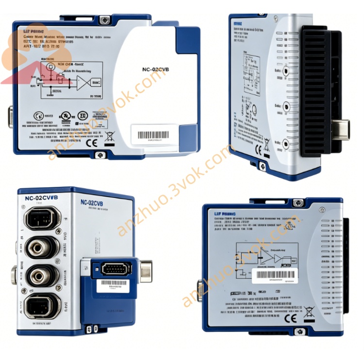
NI PXI‑2548 2.7‑GHz Quad SPDT 50‑Ohm RF Relay Module
Description
II. Model Interpretation
PXI: Compliant with the PXI bus standard, compatible with PXIe hybrid slots
2548: NI RF switch series number, representing 2.7 GHz, four-channel SPDT, electromechanical relay
Alias: NI-2548, Quad SPDT, 4-SPDT RF Switch
Position: 4-channel independent SPDT general-purpose RF switch, flexible configuration, consistent paths, medium frequency, high-density integration.
III. Technical Parameters Basic parameters
Topology: 4 independent SPDT (Single Pole Double Throw), each channel's COM can be switched to NO or NCNI
Relay type: Electromechanical latch relay (EMR)
Frequency range: DC to 2.7 GHz (–3 dB) NI
Characteristic impedance: 50 Ω (nominal) NI
Channel count: 4 independent switches, each channel has 3 RF ports (COM/NO/NC)
RF performance (typical / guaranteed values)
Insertion loss:
≤1 GHz: <0.7 dB (typical)
≤2.7 GHz: <1.0 dB (typical < 0.8 dB)
Isolation:
1 GHz: >60 dB
2.7 GHz: >50 dB
VSWR: <1.5 (within 2.7 GHz, typical <1.3)
Maximum switching power: +24 dBm (continuous)
Terminal: No built-in terminal, supports external 50 Ω load
Electrical and dynamic
Maximum switching voltage: 30 VAC / 42 VDC NI
Maximum switching current: 0.5 A (per channel) NI
Switching time: Typical 5 ms (electromechanical)
Relay lifespan: 1 million times (typical), board-mounted counter tracking NI
Scan rate: 45 times/second NI
Physics and environment
I/O connector: 12×SMA female (4 channels × 3 ports, gold-plated)
Size: 3U PXI single slot (approx. 216×20×130 mm)
Weight: Approximately 260 g
Power consumption: 12 V ≈ 0.4 W
Operating temperature: 0 to 55 °C
Storage temperature: –40 to 70 °C
IV. Interface and Communication Configuration
Front-end interface
RF interface: 12×SMA female
Each SPDT: COM (common terminal), NO (normally open), NC (normally closed)
Trigger interface: No independent trigger, supports PXI backplane hardware trigger
Bus and control
Bus interface: Standard 3U PXI mixed bus (compatible with PXIe mixed slot) NI
Control software: Compatible with NI- SWITCH, MAX, LabVIEW, TestStand, Switch Executive NI
Driver support: NI-DAQmx, NI-VISA, provides VI and API function libraries
Trigger synchronization: PXI hardware trigger, nanosecond-level synchronization, supports multi-module cascading
Configuration method: Software independently controls 4 SPDT channels, supports single-channel switching and sequence scanning
Adaptation and expansion
Adaptation cable: SMA-SMA direct connection; optional SMA to BNC/SMB/MCX conversion
Expansion capability: Multi-module cascading, builds N×N matrix or large-scale multiplexer
V. Core Functions
4 independent SPDT flexible routing: Each channel can independently switch COM to NO/NC, achieving signal splitting, combining, instrument switching or path selection, suitable for complex test topologies NI.
DC to 2.7 GHz wideband coverage: Covers Bluetooth, WiFi, ISM, 2G/3G etc. in the medium and low frequency bands, meeting consumer electronics, industrial RF and general testing requirements NI.
Path consistency and low loss: 4 electrical paths are symmetrical, insertion loss is low, ensuring multi-channel test accuracy and consistency NI.
Relay lifespan management: Board-mounted counter counts the number of switching times for each channel in real time, predicts lifespan, reduces unplanned downtime NI.
PXI standard integration: 3U size in a single slot, seamless integration into PXI chassis, supports hardware trigger synchronization, compatible with automated ATE systems NI. No built-in terminal design: Flexible external connection of 50 Ω load, suitable for high-power or custom terminal scenarios.
Six. Application Scenarios
RF signal routing and switching: Channel expansion of instruments (signal sources / spectrum analyzers / network analyzers), antenna switching, path selection between DUT and instruments.
Construction of high-channel-count multiplexer: Cascading of multiple modules to form a large-scale SPDT matrix, maintaining consistent paths, suitable for multi-DUT parallel testing with NI.
Consumer electronics RF testing: Function verification and mass production testing of Bluetooth, WiFi, NFC modules, flexible switching of test paths and loads.
Research and development laboratories and solution verification: RF link debugging, matching test, multi-solution comparison, low loss to ensure test accuracy.
Semiconductor RF chip testing: Function verification, parameter testing, aging screening of medium-low frequency RF ICs, multi-channel parallel testing.
Seven. Usage and Maintenance Instructions
Usage Points
Installation: Standard 3U PXI single slot, lock the panel, ensure reliable contact of the backplane; avoid strong vibration and electromagnetic interference.
Connection: Lightly insert and remove SMA connectors, avoid violence; RF power ≤ +24 dBm,严禁 exceeding power; unused ports are recommended to be connected with 50 Ω terminations.
Power-on State: Default each COM is connected (normally closed), NO is disconnected; without built-in terminal, external matching load is required to prevent reflection.
Software Control: Use NI-SWITCH or LabVIEW VI to control each SPDT; regularly read the relay count.
Environment: 0 - 55 °C operation, dust-proof, moisture-proof, and dew-proof; away from strong electromagnetic interference, ensure good grounding.
Maintenance Instructions
Regular Inspection: Check every quarter for any looseness, oxidation or damage of SMA connectors; clean the panel and ventilation ports, maintain good heat dissipation.
Life Management: Electromechanical relays approximately 1 million times; regularly read the onboard count, plan for replacement in advance to avoid downtime.
Fault Troubleshooting: First check SMA connection, external terminal and grounding; use MAX to diagnose switch status; take precautions against static electricity.
Storage: Power off when not in use, cover SMA connectors with a dust cap, dry and dust-proof storage, avoid high temperature, high humidity and strong magnetic fields.
Calibration: It is recommended to calibrate once a year to ensure that insertion loss, isolation, VSWR and other indicators meet specifications; you can contact NI or a third-party calibration institution.
Get a Quote