
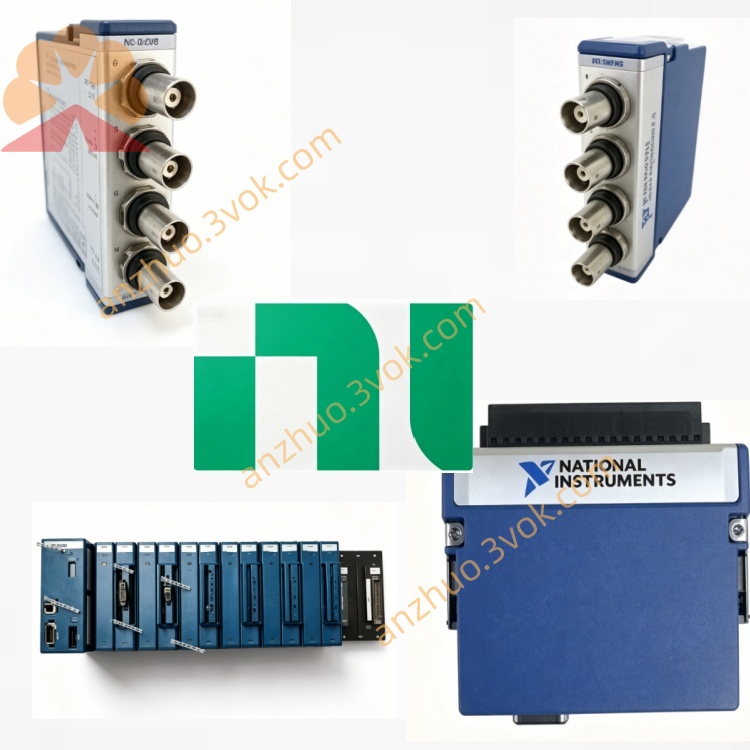
NI PXI‑2565 16‑Channel 7‑A SPST PXI Relay Module
Description
Model Explanation
PXI: PXI Bus Standard (PCI eXtensions for Instrumentation)
2565: NI Switch Module Serial Number, defined as 16-channel SPST, 7 A, 250 VAC high-power relay module
Full Name: PXI-2565 / 777754-01 → 16-Channel, 7 A, SPST PXI Relay Module
Topology Alias: NISWITCH_TOPOLOGY_2565_16_SPST (Fixed 16×SPST, cannot be reconfigured via software) NI Technical Specifications
Switch and Electrical Characteristics
Topology: 16 independent SPST (Form A, normally open), not configurable as DPSTNI
Relay Type: Electromechanical, non-latching, field-replaceable socket-type relay
Maximum Switching Voltage: 125 VDC / 250 VAC (CAT II measurement class)
Maximum Switching / Load Current: 7 A (250 VAC); 5 A (125 VDC)
Maximum Switching Power: 1750 VA (AC); 625 W (DC)
On-State Resistance (Typical): <100 mΩ
Bandwidth: DC~10 MHz
Action Time (Typical): <15 ms
Relay Lifespan:
Mechanical Life: 1×10⁷ times
Full Load Electrical Life: 1×10⁵ times (7 A / 250 VAC)
Isolation Voltage: 1400 Vrms between backplane and channel
Trigger and Control
Trigger Line: Supports PXI Trigger 0~7
Scan List: Maximum 1024 steps, supports deterministic scanning
Scan Rate: Up to 5 times/second (full channel)
Physical and Environmental
Form: Standard PXI 3U single slot
Connectors: Front panel 32-pin Mini Combicon (male), screw terminals
Dimensions (Length × Width × Height): Approximately 216×20×130 mm
Weight: Approximately 0.32 kg
Operating Temperature: 0~55°C
Storage Temperature: -20~70°C
Power Consumption (5 V): Approximately 5.5 W
Interface and Communication Configuration
Front Panel I/O
32-pin Mini Combicon (male):
16 SPST: Each channel has 1 CH (signal terminal) and 1 COM (common terminal)
Pin Assignment: CH0~CH15, COM0~COM15, a total of 32 pins (NI)
Backplane and Driver
Bus Interface: PXI Hybrid Slot (compatible with PXI-1/PXIe)
Power Supply: 5V power supply from PXI backplane
Driver Software: NI-SWITCH (IVI compatible), supports LabVIEW, TestStand, CVI, Python
Software Features: MAX identification, relay count, trigger management, scan list configuration
Core Functions
16 Independent High-Power SPST Switches: Each channel can be independently turned on or off, compatible with AC line voltage and DC power supply
High Voltage / High Current Capacity: 7 A / 250 VAC or 5 A / 125 VDC, covering most power testing requirements
On-site Replaceable Relays: Socket design, no need for factory return, reducing maintenance costs
Hardware Trigger + Deterministic Scanning: PXI backplane trigger synchronization, 1024-step scan list, improving test throughput
Relay Health Monitoring: On-board closing count, supporting predictive maintenance
High Isolation Voltage: 1400 Vrms between backplane and channel, ensuring system safety Applicable scenarios
Automotive electronic testing: ECU power circuit, load box, battery simulation, high-voltage wiring test
Industrial ATE: Power / load switching in mass production testing, relay module aging test, motor control
Energy and power: Photovoltaic module test, battery charge and discharge test, power distribution control
Military / Aviation: High-power power routing, electromagnetic coil control, onboard equipment power switching
General high-power switch: Replace mechanical switch to achieve automated programmed AC/DC power switching
User and maintenance instructions
Installation and configuration
Insert the PXI 3U single slot and fix it.
Install the NI-SWITCH driver, identify the module in MAX (topology fixed as 16-SPSST) NI.
Connect the 32-pin Mini Combicon cable. For high-power circuits, it is recommended to use multi-strand shielded wire and reliably ground.
Operation points
Power limit: Strictly follow the limits of 7 A / 250 VAC and 5 A / 125 VDC; for inductive loads (motors, coils), a rectifier diode or surge suppressor must be added to avoid overvoltage damage to contacts NI.
Trigger selection:
Low-speed debugging: Software immediate trigger;
High-speed synchronization: PXI hardware trigger (0-7 lines).
Channel independent control: 16 channels can be independently turned on and off, without interference.
Maintenance and calibration
Life monitoring: Read the number of closures through NI-SWITCH, warning for replacement when approaching 1×10⁵ times (full load).
Regular inspection: Check the Mini Combicon connector for looseness and oxidation every quarter; clean the contacts.
Environmental requirements: Working temperature 0-55°C, humidity 10%-90% (no condensation).
Relay replacement: Use the NI relay replacement kit, plug and unplug for on-site replacement, no welding required.
Get a Quote