170ADM35010
Description
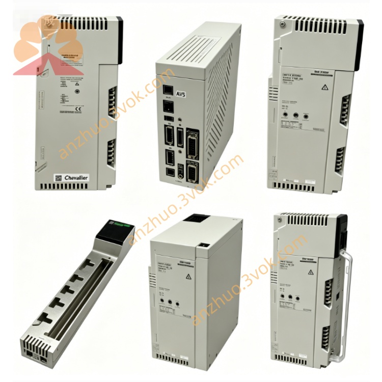
1. General Description
2. Product Identification
Model Number: 170ADM35010
Series: Modicon Momentum
Type: Discrete Solid‑State I/O Base (DC)
Channel Configuration:
1 group of 16 inputs
2 groups of 8 outputs (16 total)
Dimensions (W × D × H): 125 × 47.5 × 141.5 mm
Weight: 0.2 kg
Protection Class: IP20
Certifications: CE, UL, cUL, CSA, RoHS
Logic Type: Positive (sink) logic
3. Electrical Specifications
Inputs (16 Channels)
Rated Voltage: 24 VDC (−3 VDC to +30 VDC range)
Logic 0 (Low): −3 VDC to 5 VDC
Logic 1 (High): 11 VDC to 30 VDC
Input Current (High): ≥ 2.5 mA
Input Resistance: 4 kΩ
Response Time: 3.3 ms (1→0); ≤ 1 ms (0→1)
Standard: IEC 61131‑2 Type 1
Outputs (16 Channels, Solid‑State)
Rated Voltage: 24 VDC (≤ 30 VDC max)
Output Type: Sink (negative switching) solid‑state switch
Current per Point: 0.5 A (continuous)
Current per Group: 4 A (max)
Current per Module: 8 A (max)
Peak Current: 5 A (per point, short duration)
Leakage Current (Off): < 1 mA @ 24 VDC
Voltage Drop (On): < 0.5 V @ 0.5 A
Response Time: ≤ 0.1 ms (0→1); ≤ 2 ms (1→0)
Protection: Overload, short‑circuit (per group)
Power
Supply Voltage: 24 VDC ±10%
Current Consumption: 250 mA @ 24 VDC
Power Dissipation: ≤ 8 W
4. Environmental Ratings
Operating Temperature: 0 °C to +60 °C
Storage Temperature: −25 °C to +85 °C
Relative Humidity: 5% to 95% (non‑condensing)
Vibration: IEC 60068‑2‑6 (1 g, 10–150 Hz)
Altitude: Up to 5000 m (derate above 2000 m)
5. Features
32 LED Indicators: 16 for input status, 16 for output status
Solid‑State Outputs: No moving parts; long life, high speed
Removable Terminal Blocks: Simplifies wiring and maintenance
Snap‑On Mounting: Quick attachment to Momentum backplane
Grouped Outputs: 2 × 8 channels for fault isolation and current sharing
Overload/Short‑Circuit Protection: Per output group; automatic shutdown + LED fault indication
6. Compatibility
Backplane: Modicon Momentum I/O base rack
Adapters: 170ENT (Ethernet), 170PBM (Profibus), 170CPS (power supply) series
PLC Compatibility: Quantum, Premium, M340, Momentum controllers
7. Applications
24 VDC pushbuttons, limit switches, proximity sensors
Solenoids, contactors, relays, and small DC motors
Factory automation, material handling, infrastructure, energy systems
High‑speed, high‑reliability digital control panels
8. Installation & Wiring
Power Off: Disconnect all system power before installation.
Mounting: Snap module firmly onto Momentum backplane; ensure proper grounding.
Wiring (Inputs):
Connect 24 VDC field signals to input terminals; common (COM) per 8 inputs.
Wiring (Outputs):
Sink outputs: Connect load between positive (+24 VDC) and output terminal.
For inductive loads (solenoids, motors): Install flyback diode across load to absorb voltage spikes.
Torque: Tighten terminals to 0.5–0.6 N·m (14–22 AWG copper wire).
Verification: Check connections; power on and confirm LED status.
9. Maintenance
Periodic Inspection: Check terminal tightness and LED operation every 6 months.
Cleaning: Keep surface free of dust and contaminants.
Environment: Avoid corrosive gases, extreme vibration, or moisture.
10. Safety Notes
High Speed: Solid‑state outputs can switch fast; ensure load ratings are not exceeded.
Inductive Loads: Always use external suppression (diodes, snubbers) to protect outputs.
Qualified Personnel: Only trained electricians should perform wiring; follow local codes.
Disposal: Dispose of module per local electronic waste regulations.
Get a Quote