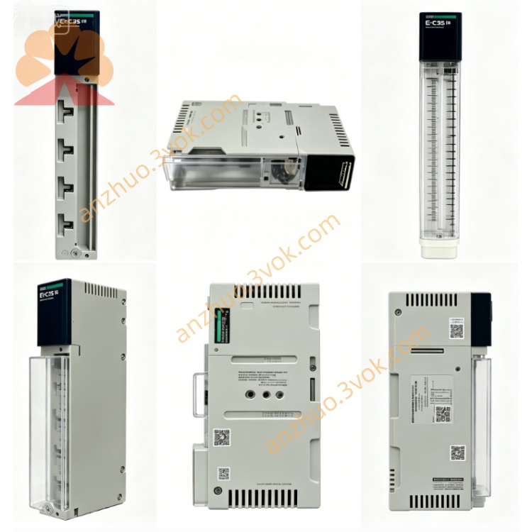
170PNT11020
Description
1. General Description
2. Product Identification
Model Number: 170PNT11020
Manufacturer: Schneider Electric (Modicon)
Product Line: Modicon Momentum (TSX Momentum)
Protocol: Modbus Plus (MB+), IEC 61131‑2 data format
Network Type: Non‑redundant (single‑cable trunk)
Ports: 1 × DB9 (RS485, MB+ compliant)
Data Rate: 1 Mbps
Power: 24 VDC (supplied via I/O base)
Power Consumption: ≤ 5 W
Dimensions: 90 mm × 160 mm × 60 mm (W×H×D)
Weight: ~0.3 kg (0.66 lb)
Mounting: DIN rail (via I/O base)
Warranty: 12 months
Status: Obsolete (replaced by 170ENT11001)
3. Electrical & Environmental Specifications
Communication Interface: 1 × DB9 female (MB+ pinout, RS485 differential)
Signaling: 1 Mbps, IEC 61131‑2 data format
Cable: Shielded twisted pair (MB+ compliant)
Max Network Length: 2,000 m (6,560 ft) without repeaters
Operating Voltage: 24 VDC ±10% (from I/O base)
Operating Temperature: -25 °C to +60 °C (-13 °F to 140 °F)
Storage Temperature: -40 °C to +85 °C (-40 °F to 185 °F)
Humidity: 5%–95% RH (non‑condensing)
Altitude: Up to 1,000 m (3,280 ft) (no derating)
Protection Class: IP20 (indoor use)
Certifications: UL, CSA, CE, RoHS, FM Class 1 Division 2
4. Compatibility
Platforms: Modicon Momentum (170 series), Quantum, Premium
I/O Bases: All Momentum I/O bases (170 series)
PLCs: Modicon Premium, Quantum, M340 (with MB+ interface)
Software: Unity Pro, MB+ Network Configurator, 984 Ladder Logic
Topologies: MB+ peer‑to‑peer, master‑slave, linear trunk/drop (single‑cable)
5. Key Features
Single‑Port MB+ (DB9): Cost‑effective for standard non‑redundant networks
IEC 61131‑2 Format: Native compatibility with Momentum and Unity Pro
1 Mbps Deterministic Speed: Real‑time data transfer for process control
Hot‑Swap Ready: Replace adapter without network shutdown
LED Status Indicators:
PWR (Green): Module powered up
MB+ ACT (Green): Network communication active
ERR (Red): Communication error or fault
DB9 Connector: Robust, industry‑standard for MB+ networks
Easy Installation: Tool‑free clip‑on mounting to I/O base
6. Applications
Distributed I/O in Momentum racks (single‑cable MB+ networks)
High‑speed PLC‑to‑I/O and PLC‑to‑PLC communication (Premium/Quantum)
Factory floor automation (material handling, packaging, process control)
Retrofit of legacy systems with modern Momentum I/O (IEC format)
Compact panel and machine‑mounted I/O solutions (cost‑optimized)
7. Installation Instructions
Power Off: Disconnect power to the Momentum I/O base.
Align Adapter: Slide the 170PNT11020 onto the I/O base’s communication connector.
Lock in Place: Press until side clips click, securing the adapter.
Connect MB+ Cable: Plug shielded DB9 cable into the adapter’s MB+ port.
Terminate Network: Install 120 Ω termination resistors at both ends of the MB+ trunk.
Power On: Restore power; verify PWR and MB+ ACT LEDs illuminate.
Configure Network: Use Unity Pro or MB+ Configurator to set the adapter’s unique MB+ address (IEC format).
8. Maintenance
Quarterly Inspection: Check DB9 connector for wear, dirt, or bent pins.
LED Check: Confirm PWR is on and MB+ ACT flashes during communication.
Cable Care: Avoid sharp bends, vibration, or stress on MB+ cables.
Shield Integrity: Ground shield at one end only (MB+ standard).
Replacement: Replace adapter if ERR is steady or communication fails (after cable/termination check).
9. Safety Precautions
Qualified Personnel: Installation/service by qualified technical staff only.
Power Disconnection: Always disconnect power before installing/removing the adapter.
Indoor Use Only: For indoor industrial environments; avoid moisture, direct sunlight.
Damage Check: Do not use if adapter, connectors, or insulation are damaged.
Disposal: Dispose per local electronic waste regulations.
10. Troubleshooting
No MB+ Communication
Confirm PWR LED is on (24 VDC power to I/O base).
Check DB9 cable is fully seated and locked.
Verify 120 Ω termination at trunk ends.
Ensure unique MB+ address (no duplicates).
Intermittent Communication
Inspect for loose DB9 connector or bent pins.
Check for excessive vibration or cable movement.
Verify shield is grounded at one end only.
Reduce network load or check for faulty nodes.
ERR (Red LED) On
MB+ network fault (short circuit, open cable, or duplicate address).
Check cable continuity and termination.
Verify no other node uses the same MB+ address.
Get a Quote