
Description
已思考
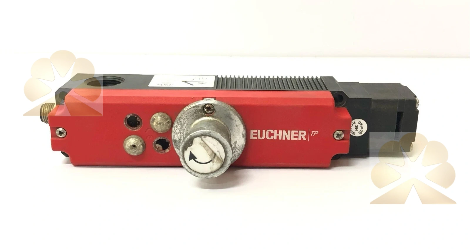
EUCHNER TP3-4141D024SEM4AS1C2238: TP ASi Guard Locking Safety Switch Product Description
Brand and Product Identification
The EUCHNER TP3-4141D024SEM4AS1C2238 is a TP series electromechanical safety switch with guard locking and integrated AS-Interface Safety at Work communication. The TP3 prefix identifies the TP3 proven plastic switch version, 4141 identifies the mechanical and contact configuration, D identifies the supply or solenoid voltage variant in this model, 024 identifies the 24 V related design, SEM4 identifies the actuator, release and contact arrangement, AS1 identifies the AS-Interface slave version, and C2238 is the special connector or option code associated with this order variant. The corresponding base TP3-4141A024SEM4AS1 design has Euchner order number 088256 and gross weight 0.464 kg.
Product Function and System Role
The safety switch monitors a machine guard door or flap and mechanically locks the guard during hazardous machine operation. The switch detects door position and guard lock state, communicates these signals over the AS-Interface bus, and controls the guard locking solenoid through the AS-i output. The auxiliary release on the front allows access to the machine in a malfunction such as a power failure using a tool or key. The device is a guard locking safety switch, not a standard door limit switch, contactor, relay, PLC, safety relay or actuator by itself; the actuator is not included.
Guard Locking Principle
The TP3 AS1 switch uses the closed-circuit current principle for power-to-unlock guard locking. The guard is locked by spring force until the guard locking solenoid is supplied with power; unlocking is performed by solenoid force. This arrangement is also described as mechanical guard locking. The guard locking solenoid is controlled via AS-Interface bit D0. To achieve safe control of the guard locking, the auxiliary voltage must also be switched safely. The AS-i auxiliary voltage supplies the guard locking solenoid.
AS-Interface Electrical Specifications
The ASI operating current is maximum 45 mA. AS-Interface auxiliary voltage range is 20.4 to 24 to 26.4 V, and auxiliary current on the AS-Interface is 300 mA. AS-Interface protocol is ASi-3. ASi voltage range is 22.5 to 24 to 31.6 V. The AS-Interface slave type has ID code B and EA code 7. ASI data output D0 controls guard locking, D1 controls the red LED and D2 controls the green LED. ASI data input D0 and D1 monitor guard position, while D2 and D3 monitor guard lock state. Solenoid duty cycle is 100 percent.
Inputs, Outputs and LEDs
AS-Interface inputs D0 and D1 monitor the guard position, and D2 and D3 monitor guard locking. AS-Interface output D0 controls guard locking, D1 controls the red LED and D2 controls the green LED. The Power LED indicates operating voltage on the bus. The Fault LED indicates a fault detected on the AS-Interface bus. The green and red LEDs can be controlled as required by the control system over the bus using bits D1 and D2. Connection uses one M12 four-pin plug connector according to the base AS1 switch design.
Mechanical and Locking Ratings
Locking force F maximum is 1300 N, and locking force F Zh is 1000 N. Extraction force is 20 N, actuating force is 10 N and retention force is 10 N. Maximum approach speed is 20 m per minute. Actuation frequency is maximum 1200 cycles per hour. Degree of protection is IP67. Contacts are silver alloy with gold flashing. The switch head approach direction is horizontal and vertical and can be adjusted in 90 degree steps. Increased overtravel is available for the horizontal approach direction.
Actuator Compatibility and Mounting
In combination with actuator ACTUATOR-P-GNT, horizontal insertion depth is 28 mm and horizontal overtravel is 7 mm. In combination with actuator ACTUATOR-P-GT, horizontal insertion depth is 28 mm, vertical insertion depth is 29.5 mm, horizontal overtravel is 2 mm and vertical overtravel is 1.5 mm. Mounting plates such as EMP-B1 are available for actuators on CTP, CTA, TPA, STA, STP, TX and TZ switches. The actuator is ordered separately. The switch and actuator must be aligned according to the Euchner dimensional drawing and machine guard geometry.
Safety Characteristics
Guard lock monitoring B10D is 3 times 10 to the power of 6, with mission time 20 years, valid at DC-13 100 mA at 24 V. Control of guard locking performance category, PL and SIL depend on external control of the guard locking in the overall safety circuit. The switch is used in an AS-i Safety at Work evaluation architecture, with door position and guard lock status evaluated by the safety monitor or controller. Installation and safety integrity must be assessed for the complete machine guard control circuit.
Typical Application Scenarios
Typical applications include machine guards on packaging machines, machine tools, presses, robotic cells, production lines, injection molding machines, conveyors, welding cells and other machinery where hazardous motion must be prevented while the door is open or unlocked. The AS-Interface version suits distributed safety networks where door position and locking status are transmitted over the AS-i bus rather than through hardwired safety relay contacts. The auxiliary release supports maintenance access during faults or power loss.
Installation and Commissioning Notes
Installation must follow the Euchner TP AS1 operating instructions, machine safety standards, AS-Interface Safety at Work guidance and local safety requirements. Mount the switch and matched actuator on the guard and frame, verify approach direction, insertion depth, overtravel and alignment, connect the M12 AS-i cable and auxiliary voltage, and configure the AS-i slave address, D-bit assignments and safety monitor parameters. Test door closed detection, locking, unlocking, auxiliary release, LED indication and fault signaling before machine release. Protect the auxiliary release against misuse with sealing or lacquer, and verify that the safety circuit safely removes hazardous motion when the guard is opened or unlocked.
Advantages and Selection Notes
The TP3-4141D024SEM4AS1C2238 offers TP3 plastic guard locking switch, spring-locked and solenoid-unlocked closed-circuit principle, AS-Interface Safety at Work communication, M12 connection, door and lock monitoring bits, LED indication, auxiliary release, 1300 N maximum locking force, IP67 protection and Euchner TP series mechanical reliability. When selecting a replacement, confirm TP3 versus TP1, TP2, TP4, TP5 or TP6 version, locking principle, supply voltage, AS-i slave code, contact and release configuration, actuator model, connector option and C2238 special code. The device is a guard locking safety switch, not a standard limit switch, safety relay, contactor, controller or actuator; its role is to monitor and lock machine guards in an AS-i safety network.
Get a Quote