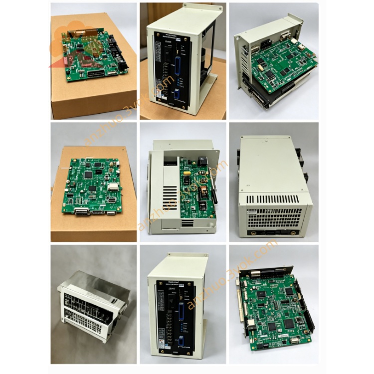
JZNC-JAU05
JZNC-JAU05 is original Yaskawa Yasnac CNC servo drive conversion interface board, matched with JANCD-JIF05 and JANCD-JIF06 communication boards, mainly applied to Yasnac J300 series CNC control cabinet for YENET bus servo drive signal conversion between CNC main control unit and external servo amplifier modules. It converts internal system bus protocol signals into dedicated drive control signals to realize real-time servo command transmission and feedback data receiving for each axis servo driver. This board has no separate standalone factory English manual, all technical content is compiled from official Yaskawa J300 system hardware maintenance specification documents.
Description
1. General Description
JZNC-JAU05 is original Yaskawa Yasnac CNC servo drive conversion interface board, matched with JANCD-JIF05 and JANCD-JIF06 communication boards, mainly applied to Yasnac J300 series CNC control cabinet for YENET bus servo drive signal conversion between CNC main control unit and external servo amplifier modules. It converts internal system bus protocol signals into dedicated drive control signals to realize real-time servo command transmission and feedback data receiving for each axis servo driver. This board has no separate standalone factory English manual, all technical content is compiled from official Yaskawa J300 system hardware maintenance specification documents.
2. Electrical and Environmental Specifications
Rated working input power is DC24V supplied from cabinet internal switching power supply, normal working current is less than 1.2A under full-load running state, built-in onboard safety fuse for input overcurrent protection with standard rated current 2A slow blow specification.
Continuous permissible operating ambient temperature ranges from 0 degree Celsius to 55 degree Celsius; storage temperature after power-off is between -20 degree Celsius and +70 degree Celsius. Applicable ambient relative humidity keeps from 5% to 95% without dew condensation inside closed electrical cabinet. Installation location must avoid dense dust, corrosive gas, oil mist and strong electromagnetic interference environment, fixed on standard rack slot inside CNC control cabinet via locking screws.
3. Connector Function Introduction
One dedicated internal bus connector is used for plugging with JANCD-JIF05/JIF06 communication board, responsible for receiving digital motion instructions, position command data and sending servo actual position feedback signal back to CNC mainboard through YENET field bus. Poor contact or loose plugging here will cause corresponding axis servo alarm or servo lost connection fault.
Another multi-core external wiring connector outputs converted analog or digital drive control signals to each servo driver terminal, transmits speed command, enable signal and fault feedback signal between conversion board and external servo unit. Improper short-circuit of external wiring may trigger onboard fuse blown and whole board stop output.
A small auxiliary terminal is reserved for system fault alarm signal output, connecting with cabinet external alarm indicator to send abnormal status signal once servo communication or conversion circuit goes wrong.
4. Installation and Replacement Operation Steps
Cut off total three-phase AC input power of entire CNC cabinet completely, wait more than five minutes for internal circuit residual capacitance voltage full discharge before disassembly work to prevent component breakdown and electric shock accident caused by residual electricity.
Mark each cable wiring position and corresponding terminal number sequentially before pulling out all connecting wires one by one, record original wiring order completely to avoid wrong wiring during reinstallation. Unscrew fixing screws at board edge then extract old JZNC-JAU05 smoothly from cabinet installation slot along plug direction.
Align new replacement board with rack mounting position and insert into slot tightly, fasten fixed locking screws firmly. Recover all connecting cables strictly following previous marked wiring sequence without cross connection or vacant terminal wiring mistake. After full wiring completion, switch on main cabinet power supply, execute system power-on self-test, verify all axes servo communication connected normally, no system servo alarm occurs, then perform manual jog test of each axis to confirm normal motion before formal equipment running.
5. Common Troubleshooting Instructions
System continuously pops up servo communication error alarm after power on: first check DC24V input voltage of JZNC-JAU05, inspect onboard protection fuse integrity and plug tightness between this board and JIF05/JIF06 communication board.
Single axis cannot execute jog movement with no servo enable signal output: check continuity of external drive signal wiring on corresponding channel of output connector, test whether related servo driver power supply is normal.
Multiple axes lose servo control simultaneously: measure whole board input power voltage and check short-circuit trouble on common output loop wiring of external servo cables.
6. Safety Precautions
Random modification of onboard original circuit layout, replacing standard specification fuse with non-rated product and arbitrarily changing factory-defined connector wiring definition are strictly forbidden. Unauthorized modification will damage bus conversion function and lead to permanent damage of CNC main control unit or servo drivers. All disassembly, replacement and maintenance operations of JZNC-JAU05 must be finished by professional maintenance technicians who master Yaskawa J300 CNC system hardware structure.
Get a Quote