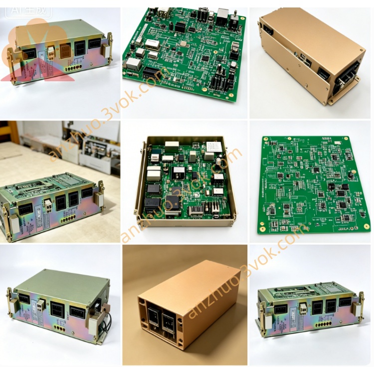
JANCV-MCP02B
JANCV-MCP02B is upgraded main CPU master control board customized for Yaskawa Motoman MRC series robot control cabinet, upgraded derivative version of JANCV-MCP01 and JANCD-MCP02 series control card, adopting backplane gold finger plug-in installation structure inside cabinet, matched with MSV series servo drive control boards, digital I/O modules and fieldbus communication boards to build full set robot motion control system. This mainboard serves as core arithmetic unit for early MRC robot controller, widely applied in automotive spot welding, arc welding, automatic material handling, component assembly and multi-station flexible automation production lines, used as core replacement spare part for maintenance and renovation of aging MRC control cabinets. All finished products pass strict industrial accelerated aging test and EMC anti-electromagnetic interference verification, conform to CE industrial safety certification standard to support long-term non-stop continuous operation under complex workshop working conditions.
Description
1. Product Overview
JANCV-MCP02B is upgraded main CPU master control board customized for Yaskawa Motoman MRC series robot control cabinet, upgraded derivative version of JANCV-MCP01 and JANCD-MCP02 series control card, adopting backplane gold finger plug-in installation structure inside cabinet, matched with MSV series servo drive control boards, digital I/O modules and fieldbus communication boards to build full set robot motion control system. This mainboard serves as core arithmetic unit for early MRC robot controller, widely applied in automotive spot welding, arc welding, automatic material handling, component assembly and multi-station flexible automation production lines, used as core replacement spare part for maintenance and renovation of aging MRC control cabinets. All finished products pass strict industrial accelerated aging test and EMC anti-electromagnetic interference verification, conform to CE industrial safety certification standard to support long-term non-stop continuous operation under complex workshop working conditions.
2. Core Functional Description
2.1 Motion & Logic Control Function
The onboard master processing chip completes full functions of robot trajectory interpolation calculation, user teaching program parsing, multi-axis servo closed-loop motion operation and peripheral equipment interlock logic judgment, maximum supports 21 servo axes synchronous linkage control, realizes dual-robot coordinated motion and external auxiliary axis follow-up control. Equipped with large-capacity onboard flash storage, it stores robot mechanical origin parameters, servo encoder calibration data, workpiece coordinate positioning data and user compiled operation programs, sufficient storage space for multi-process complex workstation batch position data saving and offline program backup. Integrated intelligent fault diagnosis system collects real-time abnormal signals including servo overcurrent, encoder wire breakage, internal bus communication failure, safety circuit disconnection and power supply abnormality, converts fault information into standardized alarm codes and transmits to handheld teach pendant for real-time display to shorten field troubleshooting cycle. Multiple independent industrial communication circuits realize bidirectional data exchange between mainboard, servo control unit, teach box and upper PLC; operators can edit programs online via teach pendant or upload/download whole project programs from external PC through dedicated debugging port. Independently processes all cabinet digital input and output signals to realize interlock control of safety door switch, fixture clamping signal, conveying equipment start-stop and peripheral auxiliary equipment linkage.
2.2 Electrical Technical Specifications
Rated input power is DC24V ±10% supplied from cabinet internal backplane bus, rated working current ≤550mA, total rated power consumption about 8W, core control circuit adopts isolated anti-surge power supply design to resist instantaneous voltage surge impact from industrial power grid fluctuation. Built-in independent fuse overcurrent protection component on PCB, automatically cuts off mainboard power supply in case of external wiring short-circuit to avoid core circuit burnout. Standard external communication interfaces include RS232 debug serial port and RS485 fieldbus terminal, compatible with mainstream industrial protocols including Modbus RTU, DeviceNet and PROFIBUS-DP for seamless connection with peripheral PLC and factory upper monitoring system. All signal access terminals add built-in surge suppression circuit to improve anti-interference performance against strong electromagnetic noise generated by welding power supply and frequency converter inside welding workshop.
2.3 Environmental Working Parameters
Normal continuous operating ambient temperature ranges from 0℃ to +55℃; spare part storage temperature is -25℃~+70℃; applicable relative humidity 30%~80%RH with non-condensing mandatory requirement. Forbidden to install in working sites containing corrosive gas, conductive metal dust, welding spatter and high-intensity electromagnetic radiation environment; protection grade IP20, only allowed to install inside sealed closed control cabinet, outdoor damp open-air installation is prohibited. Rated applicable altitude ≤1000m without power derating; adopts cabinet internal natural air convection passive heat dissipation design with no onboard built-in cooling fan. Vibration resistance standard ≤0.5G to adapt production line vibration working environment.
2.4 Hardware Interface Definition
Bottom gold finger connector directly inserts into specified backplane slot to complete DC24V power input and high-speed internal bus data communication with other functional boards inside cabinet without extra external power wiring. Front panel reserves three kinds of external fixed interfaces: exclusive teach pendant communication port, PC offline program debug serial port and fieldbus wiring terminal; hidden reserved pin terminals are specially reserved for factory original factory calibration debugging, must keep vacant without wiring under normal equipment running status.
2.5 Front Panel LED Status Definition
Green PWR steady ON indicates normal DC24V power supply from backplane; lamp OFF means slot power failure or onboard protective fuse blown. Green regular flashing RUN lamp represents normal cyclic running of CPU core system program; permanent extinguishment means system firmware damage or mainboard hardware breakdown. Intermittent flashing yellow COM lamp means stable data communication with teach pendant and external field equipment; continuous OFF status caused by broken communication cable or mismatched bus configuration parameters. Steady red ERR lamp lights for severe system faults including lost core parameter data, servo bus disconnection and mainboard hardware damage; short intermittent flickering mostly triggered by accidental external safety signal action or instantaneous industrial electromagnetic interference.
3. Installation, Commissioning & Maintenance Specification
3.1 Replacement Installation Steps
Cut off total AC input power of control cabinet before any disassembly and replacement operation, wait more than 15 minutes for full discharge of high-voltage electrolytic capacitor inside cabinet to prevent residual voltage breakdown of onboard electronic components. Align PCB gold finger with corresponding backplane slot and insert horizontally smoothly, lock fixed buckle tightly, fasten all front panel external communication connecting wires to eliminate virtual connection and poor contact risk. After hardware installation and power on, MRC controller automatically identifies JANCV-MCP02B hardware information; when replacing blank new mainboard, import original robot backup parameters and user application programs via teach pendant or external computer, finish single-axis origin calibration of all servo axes item by item before equipment trial operation and formal production.
3.2 Common Fault Troubleshooting
PWR indicator always off: firstly measure DC24V voltage of corresponding backplane slot, check integrity of onboard fuse, replace fuse with same specification and re-plug mainboard to eliminate poor gold finger contact caused by oxidation dust accumulation. Normal power supply but RUN lamp unlit: clean gold finger contact surface with anhydrous alcohol, dry thoroughly and reinstall; if fault persists, confirm mainboard internal hardware damage requiring integral replacement. ERR constant lighting: firstly check peripheral servo driver, safety switch and external wiring failure; if peripheral circuit is intact, judge mainboard internal circuit damage. COM lamp no flashing and teach pendant offline: inspect communication cable breakage and terminal loose condition, rewire and reset bus communication parameters.
3.6 Routine Maintenance Requirements
All plugging, disassembly and maintenance operations must be completed under full power-off state of control cabinet. Implement regular maintenance every six months, wipe accumulated dust on PCB surface with dry lint-free cloth, inspect aging and loose external connecting cables periodically. Keep cabinet internal dry and clean in long-term running to avoid PCB copper layer corrosion and short-circuit failure caused by damp environment; arbitrary disassembly of onboard discrete components for partial maintenance is forbidden once mainboard hardware damage is confirmed, integral replacement is the official recommended solution.
4. Application Scope
Main matching applicable equipment: full range Yaskawa Motoman MRC series industrial robot controller, including spot welding robot, arc welding robot, handling robot and multi-joint assembly robot supporting MRC control system, widely used in automobile manufacturing, household appliance automation processing, metal processing automatic production industry.
Get a Quote