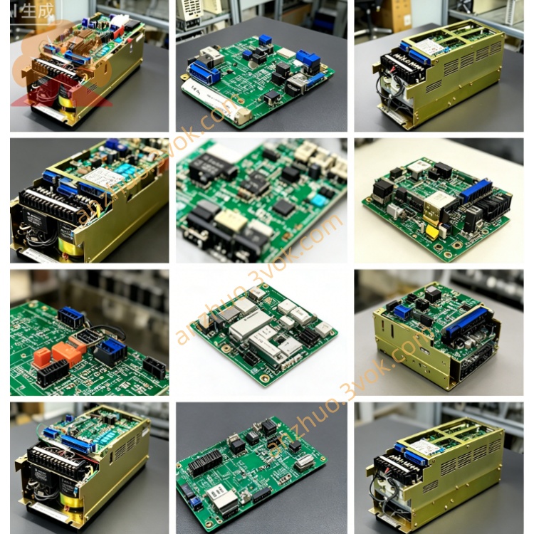
JANCU-MSV01B
JANCU-MSV01B is original Yaskawa Motoman dedicated servo axis control board, matching XRC/MRC robot controller cabinet, used together with JANCU-MCP series main CPU board as core servo signal processing unit of robot control system. It adopts plug-in gold finger structure to be fixed on cabinet internal backplane slot, responsible for high-speed instruction transmission between main control CPU and each axis servo amplifier, converts motion interpolation commands from mainboard into servo drive control signals, collects real-time motor encoder feedback data to form closed-loop axis control. Widely configured on spot welding, arc welding, handling and assembly Motoman old-series industrial robots, it is the core replacement spare part for cabinet servo channel failure maintenance, fully conforms to industrial CE safety standard and strict factory anti-interference aging test for long-term continuous workshop operation.
Description
1. Product Brief Introduction
JANCU-MSV01B is original Yaskawa Motoman dedicated servo axis control board, matching XRC/MRC robot controller cabinet, used together with JANCU-MCP series main CPU board as core servo signal processing unit of robot control system. It adopts plug-in gold finger structure to be fixed on cabinet internal backplane slot, responsible for high-speed instruction transmission between main control CPU and each axis servo amplifier, converts motion interpolation commands from mainboard into servo drive control signals, collects real-time motor encoder feedback data to form closed-loop axis control. Widely configured on spot welding, arc welding, handling and assembly Motoman old-series industrial robots, it is the core replacement spare part for cabinet servo channel failure maintenance, fully conforms to industrial CE safety standard and strict factory anti-interference aging test for long-term continuous workshop operation.
2. Detailed Product Specification & Function Description
2.1 Core Functional Characteristics
This axis control board undertakes all servo command forwarding and feedback signal collection work inside robot cabinet, supports maximum total 21 servo axes coordinated motion control and dual robot synchronous linkage operation. It receives trajectory interpolation data calculated by main CPU board via internal backplane bus, distributes position, speed and torque control instructions to corresponding single-axis servo driver in real time, meanwhile receives absolute encoder and incremental encoder feedback signals from each servo motor, feeds actual axis position data back to mainboard for closed-loop position correction to guarantee robot repeated positioning precision. The board carries built-in hardware fault detection circuit, real-time monitors servo overcurrent, overvoltage, encoder disconnection and communication break abnormal state, once fault occurs it immediately uploads alarm information to main control board and displays corresponding error code on handheld teach pendant. Besides standard servo signal processing, it reserves extended signal channel to connect external auxiliary servo axis for peripheral fixture and sliding table servo linkage control of automation workstation.
2.2 Electrical Performance Parameter
Power supply comes from cabinet backplane DC24V ±10% bus power supply, normal working average current is below 480mA, overall power consumption about 6.5W, internal control circuit adopts isolated power supply design to restrain industrial site power grid surge and electromagnetic interference. Multiple groups of dedicated differential signal circuits are equipped for encoder signal transmission, anti-interference capability is optimized for complex welding workshop high-frequency magnetic field environment; onboard installs independent fast blow protection fuse to avoid whole board burnout caused by external servo wiring short-circuit fault. External front panel multi-channel dedicated servo communication interfaces adopt shielded wiring design, matched with original servo signal cable to realize stable high-speed data interaction between board and servo unit, part reserved debugging pin interfaces are only used for factory parameter calibration and daily maintenance debugging, no wiring under normal production operation.
2.3 Environmental Working Conditions
Continuous working ambient temperature range is 0℃~+55℃, spare part sealed storage temperature scope is -25℃~+70℃; applicable working environment relative humidity keeps 30%~80%RH under non-condensing state, strictly forbidden to arrange in environment with corrosive gas, conductive metal dust, welding splash and strong electromagnetic radiation near high-power inverter and welding power source. Protection grade is IP20, only allowed to install inside closed robot electric control cabinet, cannot be used in open damp outdoor environment; rated applicable working altitude is below 1000 meters without derated use, adopts passive natural heat dissipation mode without built-in cooling fan, relies on cabinet internal circulating air to complete component heat dissipation.
2.4 Interface Definition Description
Bottom gold finger bus connector inserts into specified backplane slot, finishes DC24V power input and high-speed internal bus data exchange with main CPU board and other functional modules, no extra external wiring needed for this part. Front panel arranges multiple groups of dedicated servo signal terminals respectively corresponding each robot servo axis, used for connecting servo driver encoder feedback cable and command control cable; one reserved small debugging port is factory exclusive download interface, vacant during normal equipment running. All external signal terminals are equipped with locking buckle structure to prevent wiring loose caused by equipment vibration during long-time operation.
2.5 Panel LED Indicator Definition
Green PWR indicator steady on means backplane DC24V power supply input is normal, lamp extinguishment represents slot power loss or onboard protection fuse blown due to short circuit damage. Green RUN intermittent flicker stands for normal data transmission between this board and main CPU, constant off means internal bus communication failure or core hardware breakdown. Yellow SERV lamp flicker in sync with servo motor running to represent normal signal interaction with corresponding axis servo driver, long-time off indicates single axis servo cable break or driver power failure. Red ERR steady lighting triggers when encoder fault, servo overcurrent or channel hardware damage occurs, short intermittent flicker is temporary signal interference or transient overload protection action of peripheral servo equipment.
2.6 Installation and Commissioning Steps
All disassembly and replacement operations must cut off cabinet total AC power and wait more than 15 minutes for internal high-voltage capacitor full discharge to prevent residual voltage damaging PCB electronic components. Align PCB bottom gold finger with designated empty backplane slot and push horizontally until fixed buckle locks tightly, connect each front panel servo signal cable one by one and fasten terminal lock catch to avoid virtual connection. After installation completes and cabinet powers on, system automatically identifies JANCU-MSV01B hardware; if replaced with new blank board, it is required to enter system parameter page via teach pendant to reload original servo gain parameters and each motor encoder origin data, carry out robot each axis zero-point calibration before formal trial run and production.
2.7 Common Fault Troubleshooting
PWR lamp always off: detect backplane corresponding slot DC24V output voltage and check onboard built-in fuse integrity, replace damaged fuse with same specification then reinsert the board and test. RUN lamp off with normal power supply: mostly caused by gold finger dust contamination or poor contact, wipe gold finger with anhydrous alcohol and reinstall; if fault persists it means board internal circuit damage needing whole replacement. Single channel SERV lamp always off and corresponding axis alarm: inspect servo connecting cable breakage and servo driver power supply condition, peripheral equipment normal then confirm corresponding channel circuit fault of this control board. ERR lamp continuous lighting: check each axis encoder wiring short or break, after eliminating peripheral wiring problem it is judged as onboard channel hardware failure.
2.8 Daily Maintenance Specification
All maintenance and cable plugging work must be finished under full cabinet power-off state. Carry out semi-annual regular maintenance, use dry lint-free cloth to wipe PCB surface accumulated dust, check aging and loosening of all front panel servo connecting cables, tidy scattered wiring to avoid cable extrusion damage. Do not arbitrarily disassemble onboard original electronic components after board damage, official recommended maintenance scheme is complete board replacement; keep cabinet inner space dry and clean to prevent PCB copper layer corrosion and short-circuit failure caused by damp air.
Get a Quote