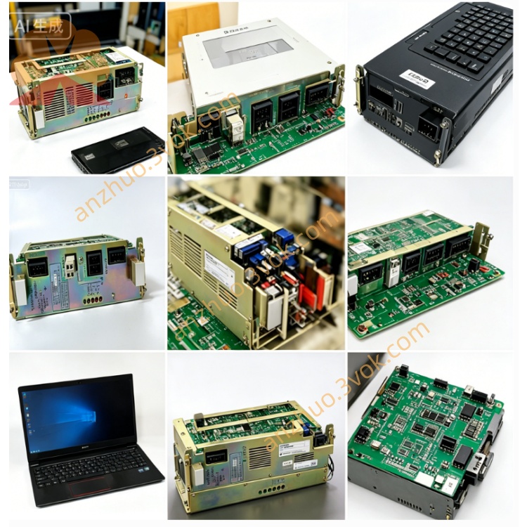
JANCU-MCP02B
JANCU-MCP02B is original Yaskawa Motoman dedicated main CPU control board, upgraded version of JANCU-MCP01, matching MRC/XRC series robot controller cabinet platform, serving as core central processing unit of the whole robot control system. This card adopts standard plug-in backplane insertion structure, cooperates with servo drive board, safety signal board, I/O expansion board and cabinet backplane to build complete robot motion control architecture, widely applied in spot welding, arc welding, automatic handling, component assembly and stamping automation Motoman industrial robots, and is mainstream spare replacement part for old XRC/MRC cabinet maintenance upgrade. Optimized on the basis of predecessor MCP01 in arithmetic speed, storage capacity and external bus compatibility, it enhances multi-axis compound motion operation stability and peripheral equipment docking expansibility, passed CE industrial safety certification and industrial anti-interference test for long-term continuous factory operation.
Description
1. Product Brief Introduction
JANCU-MCP02B is original Yaskawa Motoman dedicated main CPU control board, upgraded version of JANCU-MCP01, matching MRC/XRC series robot controller cabinet platform, serving as core central processing unit of the whole robot control system. This card adopts standard plug-in backplane insertion structure, cooperates with servo drive board, safety signal board, I/O expansion board and cabinet backplane to build complete robot motion control architecture, widely applied in spot welding, arc welding, automatic handling, component assembly and stamping automation Motoman industrial robots, and is mainstream spare replacement part for old XRC/MRC cabinet maintenance upgrade. Optimized on the basis of predecessor MCP01 in arithmetic speed, storage capacity and external bus compatibility, it enhances multi-axis compound motion operation stability and peripheral equipment docking expansibility, passed CE industrial safety certification and industrial anti-interference test for long-term continuous factory operation.
2. Detailed Product Performance & Functional Description
2.1 Core Control Functions
The onboard main processing chip undertakes full robot trajectory interpolation operation, program parsing, servo closed-loop operation calculation and peripheral interlock logic processing, maximum supports 21 servo axes linkage control, realizes dual-robot coordinated synchronous running and external servo axis follow-up control. Built-in large-capacity flash memory stores user teaching programs, coordinate position data, system original parameters and servo calibration data, storage space is promoted compared with MCP01, can store more than 5000 groups of workpiece positioning coordinate data to satisfy complex multi-station production programming demand. Independently processes all cabinet digital input and output signals, completes safety door, fixture clamping, conveyor interlock and peripheral alarm signal logic judgment, realizing automatic start-stop linkage of whole automation workstation. Multiple built-in industrial communication circuits finish bidirectional data exchange with servo unit, handheld teach pendant and upper computer, supports program online modification via teach box and offline program upload/download through external PC debugging port, meanwhile integrates real-time fault diagnosis function to collect servo overcurrent, overtravel, communication abnormity and hardware fault information, feeds corresponding alarm codes to teach pendant screen for rapid troubleshooting.
2.2 Electrical Parameter Specification
The board is powered by cabinet backplane DC24V ±10% direct power supply, rated average working current is below 520mA, rated overall power consumption about 7.5W, internal core circuit adopts isolated power supply design to resist instantaneous power grid surge fluctuation in industrial field. Onboard is equipped with independent overcurrent protection fuse to prevent PCB burnout caused by external wiring short-circuit fault. External communication interfaces include standard RS232 serial port, RS485 bus interface and reserved field bus expansion terminal, compatible with Modbus RTU, DeviceNet mainstream industrial communication protocols to connect external PLC, auxiliary automation equipment and upper monitoring host. All signal ports adopt anti-surge protection circuit to improve adaptability under complex factory power environment.
2.3 Environmental Working Conditions
Normal continuous operating ambient temperature range is 0℃~+55℃, spare part storage temperature scope is -25℃~+70℃; applicable working relative humidity is 30%~80%RH under non-condensing state, prohibited to install in environment with corrosive gas, conductive dust, welding spatter and strong electromagnetic interference near high-power inverter and welding equipment. It is designed for IP20 protection grade, only allows installation inside closed robot control cabinet, cannot be used in open damp outdoor environment; applicable working altitude is below 1000 meters without derated load operation, passive natural air cooling mode without built-in cooling fan, relying on cabinet internal air circulation to complete heat dissipation.
2.4 Onboard Connector Definition
Bottom gold finger bus connector directly inserts into designated slot of cabinet backplane, responsible for DC24V power input and high-speed internal bus data transmission with each functional board inside cabinet, no extra external wiring needed for this interface. Front panel external interfaces contain teach pendant dedicated communication port for handheld programming device connection, RS232 debugging port for factory program brushing and maintenance parameter calibration, field bus terminal port for peripheral PLC wiring connection, and a hidden factory exclusive debugging pin which keeps vacant under normal production running condition without wiring.
2.5 Onboard LED Indicator Explanation
Green PWR indicator steady on means backplane DC24V power input is normal, lamp off represents slot power supply failure or onboard protection fuse blown caused by short-circuit damage. Green RUN periodic flicker indicates CPU operates normally and system cyclic program runs smoothly, permanent extinguishment means core program crash or mainboard hardware damage. Orange COM lamp intermittent flashing stands for normal data communication with teach pendant and external peripheral equipment, long-time off means communication cable breakage or bus parameter setting mismatch. Red ERR steady lighting triggers under serious system faults including parameter loss, servo bus disconnection and mainboard hardware breakdown; intermittent short flicker belongs to temporary signal interference or abnormal trigger of external safety interlock signal.
2.6 Installation & System Setting Steps
All disassembly, replacement and wiring operations must completely cut off cabinet AC main power and wait over 15 minutes for internal high-voltage capacitor full discharge to avoid residual voltage damaging onboard electronic components. Align PCB gold finger with designated empty slot of cabinet backplane and insert horizontally until locking buckle is fully fixed, check all front panel external wiring terminals for fastening without loose and virtual connection. After finishing installation and cabinet power-on restart, XRC/MRC controller automatically identifies MCP02B mainboard hardware; when replacing blank new mainboard, users need to import original robot backup parameter file and teaching programs via teach pendant or external computer, finish each robot axis zero-point calibration before formal equipment production operation.
2.7 Common Fault Troubleshooting Guide
PWR lamp always keeps off: firstly detect backplane corresponding slot DC24V output voltage value and check onboard built-in protection fuse integrity, replace with same specification fuse after damage, pull out and reinstall mainboard to eliminate poor gold finger contact fault. RUN lamp extinguished with normal power supply: mostly caused by contaminated gold finger contact or system program missing, wipe gold finger with anhydrous alcohol and reload backup system program after reinstallation. ERR constant lighting: pre-check all servo driver and peripheral safety switch for abnormity triggering, if peripheral equipment is intact then confirm mainboard internal hardware damage and replace whole board. COM lamp no flicker and teach pendant cannot connect main control: inspect communication cable breakage and interface loose condition, reset bus communication parameter after rewiring.
2.8 Daily Maintenance Precautions
All maintenance and component disassembly work must be implemented under cabinet full power-off state. Regular maintenance every six months, use dry soft lint cloth to clear accumulated dust on PCB surface, inspect aging and looseness of all external connecting cables. Once mainboard hardware is confirmed damaged, whole-unit replacement is official recommended maintenance plan, prohibited to arbitrarily disassemble onboard original discrete components for partial repair. Keep cabinet inner space dry and clean during long-term equipment operation, avoid damp and corrosive environment leading to PCB copper corrosion and circuit short-circuit failure.
Get a Quote