JANCU-MCP01
JANCU-MCP01 is original Yaskawa main CPU control board belonging to XRC/MRC old-generation robot controller platform, serving as core arithmetic and program processing unit inside robot control cabinet, matched with servo drive board, safety I/O board and backplane to form complete robot control system. It undertakes full robot motion operation calculation, teach program parsing, external I/O logic processing and multi-device communication scheduling, supports dual-robot synchronous linkage control and multi-axis coordinated motion, widely used for traditional spot welding, handling, assembly Yaskawa XRC series industrial robot equipment, and is the core replacement spare part for after-sales maintenance of old-model robot cabinets. This board adopts plug-in card structure for cabinet backplane slot installation, follows industrial grade component standard and has passed CE safety certification for industrial field application.
Description
1. Product Brief Introduction
JANCU-MCP01 is original Yaskawa main CPU control board belonging to XRC/MRC old-generation robot controller platform, serving as core arithmetic and program processing unit inside robot control cabinet, matched with servo drive board, safety I/O board and backplane to form complete robot control system. It undertakes full robot motion operation calculation, teach program parsing, external I/O logic processing and multi-device communication scheduling, supports dual-robot synchronous linkage control and multi-axis coordinated motion, widely used for traditional spot welding, handling, assembly Yaskawa XRC series industrial robot equipment, and is the core replacement spare part for after-sales maintenance of old-model robot cabinets. This board adopts plug-in card structure for cabinet backplane slot installation, follows industrial grade component standard and has passed CE safety certification for industrial field application.
2. Detailed Product Content
2.1 Core Functional Characteristics
The main control chip inside the board completes real-time trajectory interpolation calculation of robot axes, maximum supports total 21 servo axes control and realizes synchronous motion of two independent robots at the same time. It stores user-written robot teaching programs, position coordinate data and system original parameters in onboard flash memory, with fixed storage capacity for about 2200 sets of positioning coordinate data to satisfy conventional production process programming demands. It processes digital input and output signal interlock logic between robot and peripheral fixture, safety door, conveyor line, realizing automatic startup and stop linkage of whole automation workstation. Meanwhile the board integrates multiple bus communication circuits, completes data interaction with servo control unit, teach pendant and upper industrial host, supports offline program uploading from external computer and online program modification via teach box. Built-in fault diagnosis algorithm can automatically collect abnormal signals of servo overcurrent, overtravel and communication breakdown, generate corresponding alarm codes and feed back fault information to teach pendant display for quick maintenance troubleshooting.
2.2 Electrical Specification
The board is powered by cabinet backplane DC24V ±10% power supply, maximum working current is controlled below 500mA and average power consumption keeps around 7W. All internal core circuits adopt isolated power supply design to resist instantaneous voltage fluctuation of industrial power grid. External signal ports contain general-purpose digital I/O channel resources for peripheral switching signal access, communication circuits are compatible with Modbus RTU, DeviceNet and PROFIBUS-DP common industrial bus protocols to connect different brand peripheral automation equipment. Onboard sets built-in overcurrent protection component to avoid circuit burnout caused by external short-circuit wiring fault.
2.3 Environmental Working Conditions
Normal continuous operating ambient temperature ranges from 0°C to +60°C, spare part storage temperature scope is -25°C to +70°C; applicable working relative humidity is 30%~80%RH under non-condensing environment, cannot be placed in environment with corrosive gas, conductive dust, welding splash and strong electromagnetic interference near high-power inverter and welding equipment. It is applicable for installation environment below altitude 1000 meters without derated use, protection grade is IP20, only suitable for closed robot control cabinet inner installation, forbidden to use in open-air exposed environment. The board uses passive natural heat dissipation without built-in cooling fan, relying on cabinet internal air circulation to complete heat dissipation.
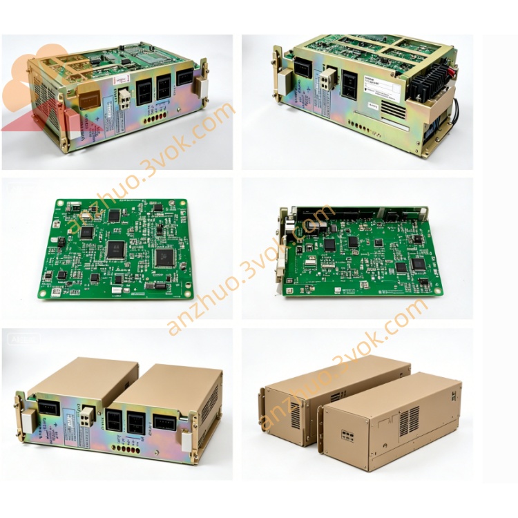
2.4 Onboard Connector Definition
Gold finger bus connector at the board bottom inserts into cabinet dedicated backplane slot, responsible for DC24V power input and high-speed internal bus data exchange with servo board, safety board and other functional modules, no extra external wiring needed for this port. Front panel external interface contains teach pendant communication port for handheld programming box connection, serial debugging port reserved for factory program download and parameter calibration during maintenance, and field bus terminal port for external PLC and peripheral equipment communication wiring. Small reserved auxiliary pin port is factory exclusive debugging interface and remains vacant during normal on-site running.
2.5 Onboard LED Indicator Description
Green PWR indicator lights steadily when backplane DC24V power supply is normally input, lamp off means slot power failure or onboard protection circuit triggered by short circuit. Green RUN flickers periodically to represent normal CPU operation and cyclic program running, constant extinguishment stands for main program crash or core hardware damage. Orange COM lamp flashes intermittently during normal communication with teach pendant and external equipment, long off indicates communication line break or bus parameter mismatch. Red ERR steady lighting represents system serious fault such as parameter loss, axis communication failure or mainboard hardware breakdown, short intermittent flicker belongs to temporary signal interference or abnormal peripheral I/O trigger.
2.6 Installation and System Configuration Instruction
All disassembly and replacement operations must cut off cabinet total AC power and wait over 15 minutes for cabinet internal high voltage capacitor full discharge to prevent residual voltage damaging PCB components. Align board gold finger with specified empty backplane slot and insert horizontally until fixed buckle locks tightly in place, confirm all front panel external wiring terminals are fastened without loose. After installation finishes and cabinet powers on, the controller automatically identifies JANCU-MCP01 mainboard and loads default system parameters; when replacing new blank mainboard, need to import original robot backup program and axis calibration parameters via teach pendant or external computer, finish zero-point calibration of each axis before formal production operation.
2.7 Common Fault Troubleshooting
PWR lamp always off: check cabinet backplane corresponding slot DC24V output voltage and onboard built-in protection fuse status, replace damaged fuse with same specification and re-plug the mainboard for testing. RUN lamp off with normal power supply: mostly caused by poor gold finger contact or mainboard program loss, clean gold finger with anhydrous alcohol and reload system backup program after reinstallation. ERR lamp continuous lighting: firstly confirm no servo driver hardware fault and peripheral safety interlock switch abnormal triggering, if peripheral equipment is normal then mainboard internal hardware damage needs whole-board replacement. COM lamp no flicker and teach pendant cannot connect: inspect communication cable breakage and front port terminal loose condition, reset bus communication parameter setting after rewiring.
2.8 Daily Maintenance Points
All maintenance and wiring work must be operated under full power-off status of robot control cabinet. Carry out regular maintenance every half a year, use dry lint-free cloth to wipe accumulated dust on PCB surface and check aging and looseness of all external connection cables. Do not arbitrarily disassemble onboard original electronic components after mainboard damage, integral replacement is the official recommended maintenance scheme. Avoid long-term exposure of cabinet to damp environment to prevent PCB copper layer corrosion and circuit short failure.
Get a Quote