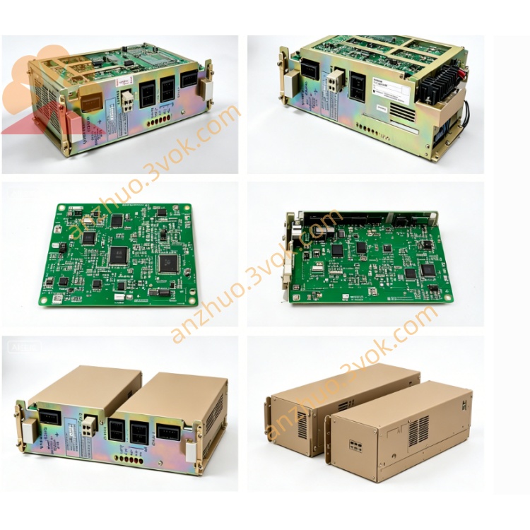
JANCD-YSF25
JANCD-YSF25-E is Yaskawa original advanced functional safety monitoring board belonging to YSF safety series, specially designed for DX200 robot control cabinet and partially compatible with YRC1000 compact robot controller platform, complying with IEC61508 SIL3 and EN ISO Category3 functional safety standard, used as high-end safety expansion module matching basic safety mainboard JANCD-YSF22-E and expansion safety board JANCD-YSF24-E. Different from conventional YSF22 and YSF24 which mainly process external switch safety signals, YSF25 focuses on real-time dynamic monitoring of robot axis actual operating status, motion speed and spatial working boundary, serving core safety certification for collaborative robot application, limited space working and speed restricted production lines, installed on reserved dedicated slot of YBB21 cabinet backplane together with main CPU JANCD-YCP21 and servo interface JANCD-YIF01 board to complete full-system hierarchical safety control architecture inside cabinet.
Description
1. Product Brief Overview
JANCD-YSF25-E is Yaskawa original advanced functional safety monitoring board belonging to YSF safety series, specially designed for DX200 robot control cabinet and partially compatible with YRC1000 compact robot controller platform, complying with IEC61508 SIL3 and EN ISO Category3 functional safety standard, used as high-end safety expansion module matching basic safety mainboard JANCD-YSF22-E and expansion safety board JANCD-YSF24-E. Different from conventional YSF22 and YSF24 which mainly process external switch safety signals, YSF25 focuses on real-time dynamic monitoring of robot axis actual operating status, motion speed and spatial working boundary, serving core safety certification for collaborative robot application, limited space working and speed restricted production lines, installed on reserved dedicated slot of YBB21 cabinet backplane together with main CPU JANCD-YCP21 and servo interface JANCD-YIF01 board to complete full-system hierarchical safety control architecture inside cabinet.
2. Detailed Product Specification & Functional Description
2.1 Core Working Functions
This board adopts dual-core redundant safety operation circuit, directly reads real-time encoder position and speed feedback data from each servo axis via internal backplane high-speed bus instead of external discrete switch input, executes independent safety arithmetic judgment offline without relying on main CPU calculation. Its core realized functions include real-time single-axis travel range overrun protection, multi-axis composite space boundary limit monitoring, robot TCP actual movement speed real-time surveillance and overspeed interlock, robot tool installation posture angle abnormal monitoring as well as tool quick-change state safety detection; once actual robot motion parameter exceeds preset safety threshold, the board immediately sends independent servo cutoff instruction to JANCD-YIF01 servo interface board to realize partial axis deceleration limit or full servo power cutoff, meanwhile feeds fault safety codes back to robot main control system and outputs linkage alarm signal to peripheral automation equipment for production line interlock stop. All monitoring logic follows redundant dual-channel verification rule to avoid safety malfunction caused by single internal circuit failure, which is the core hardware for robot safety restricted zone and human-machine collaborative operation certification.
2.2 Electrical Performance Parameter
The board is powered by DC24V ±10% power supplied directly from YBB21 backplane slot, maximum rated power consumption is roughly 13W, equipped with built-in 1.2A slow-blow safety fuse for onboard overcurrent protection. No large quantity of external digital I/O is arranged onboard; reserved auxiliary signal port supports small quantity DC24V sink/source universal safety input for external auxiliary fixture interlock signal collection, each input rated operating current is between 3mA and 5mA, valid signal is DC24V access and invalid for open circuit state; onboard isolated safety output supports DC24V 0.4A maximum load for external safety alarm and equipment interlock driving use.
2.3 Environmental Application Condition
Standard allowable operating ambient temperature ranges from minus 10 degrees Celsius to positive 55 degrees Celsius, storage environment temperature covers minus 25 degrees Celsius to positive 70 degrees Celsius; applicable working humidity is 30% to 80% relative humidity under non-condensing environment, cannot be installed in space with welding flammable splash, corrosive chemical gas, conductive dust and high-frequency electromagnetic interference generated by welding machine or high-power inverter equipment. The board uses passive natural convection heat dissipation design without built-in cooling fan, relying on cabinet internal circulating air to complete heat exchange.
2.4 Onboard Connector Definition
CN200 gold finger connector directly inserts into YBB21 backplane slot, responsible for bidirectional high-speed data exchange with main CPU YCP21, YSF22 safety mainboard and YIF01 servo board to acquire real-time axis encoder feedback data, no extra external wiring required. CN220 is reserved external auxiliary safety I/O connector, matched with separate terminal adapter for field connection of peripheral auxiliary safety switch signals such as fixture locking confirmation and external safety zone proximity switch. Another hidden factory debugging connector is only used for manufacturer maintenance calibration and remains vacant under regular on-site running status.
2.5 Onboard LED Indicator Definition
Green PWR indicator represents board power supply status, steady lighting means DC24V input from backplane is normal, lamp off indicates onboard fuse burnout or backplane corresponding slot power supply fault. Green RUN lamp reflects backplane bus communication state, slow periodic flashing stands for normal real-time data interaction with servo and main control boards, permanent extinguishment means backplane poor contact or internal bus communication breakdown. Orange SAFE lamp shows overall safety monitoring loop state, constant on means all axis motion parameters stay within preset safety limit and safety monitoring function is ready; lamp off represents any axis exceeds speed or space boundary and safety interlock is triggered. Red ERR fault lamp keeps steady on when dual redundant internal operation data inconsistency, parameter setting mismatch or onboard hardware circuit fault occurs; intermittent flashing means external auxiliary input wiring short/open or DIP switch configuration error.
2.6 DIP Switch Configuration Instruction
S1 DIP coding switch is set on PCB surface, all parameter adjustment must be operated under complete cabinet main power cut-off and internal high-voltage capacitor full discharge for more than 15 minutes. BIT1 and BIT2 define hardware station address of YSF25 on backplane bus, factory default fixed address matched with DX200 system and arbitrary modification is forbidden. BIT3 is used for tool angle monitoring logic definition, ON corresponds to high-level effective trigger mode and OFF matches normally closed contact open trigger setting. BIT4 to BIT6 belong to factory reserved configuration pins and need to keep OFF position permanently without random adjustment.
2.7 Installation and System Software Setting Steps
Before physical installation, disconnect cabinet AC main power completely and wait for residual high voltage releasing, finish DIP switch setting according to on-site robot safety specification requirement. Align PCB gold finger with specified vacant slot on YBB21 backplane and insert tightly until locking buckle is fixed in place; complete peripheral auxiliary safety switch wiring at CN220 connector and do single-point grounding of shielding cable on cabinet earth bar. After wiring completion, restore cabinet power supply, DX200 controller automatically identifies YSF25 hardware during system startup without manual hardware option activation via teach pendant. After new board replacement finishes and system reboot, original safety parameter data automatically loads from system storage; users can modify safety speed limit and spatial boundary parameters through teach pendant menu path of system safety setup and functional safety configuration page.
2.8 Common Troubleshooting Guidance
When PWR indicator keeps off all the time, first check internal 1.2A fuse damage condition and replace with same specification slow-blow fuse, then pull out and reinsert YSF25 board to eliminate poor gold finger contact and measure backplane slot DC24V power supply voltage. If SAFE lamp permanently off and robot cannot operate at rated speed, enter teach pendant safety setting page to check axis speed and space limit parameter configuration, meanwhile confirm no external auxiliary safety switch is triggered abnormally. Red ERR steady lighting is mainly caused by mismatched DIP setting or internal dual-channel operation data inconsistency, need to recheck switch configuration and restart controller after power-off reset. RUN lamp off with normal power supply is mostly caused by contaminated gold finger or backplane slot damage, clean PCB contact position with anhydrous alcohol and reinstall the board again.
2.9 Daily Maintenance Precautions
All disassembly, wiring and maintenance operations must be finished under full cabinet power-off state to avoid residual voltage damaging circuit components. Implement routine maintenance every six months, clean accumulated dust on PCB surface with dry soft cloth and inspect connector looseness and cable insulation aging condition. Once the board is confirmed internal hardware damaged, whole unit replacement is recommended and unauthorized disassembly of onboard discrete electronic components for partial repair is prohibited. During long-term equipment operation, keep the board away from welding arc splash, moisture and strong electromagnetic radiation working environment to extend service life.
Get a Quote