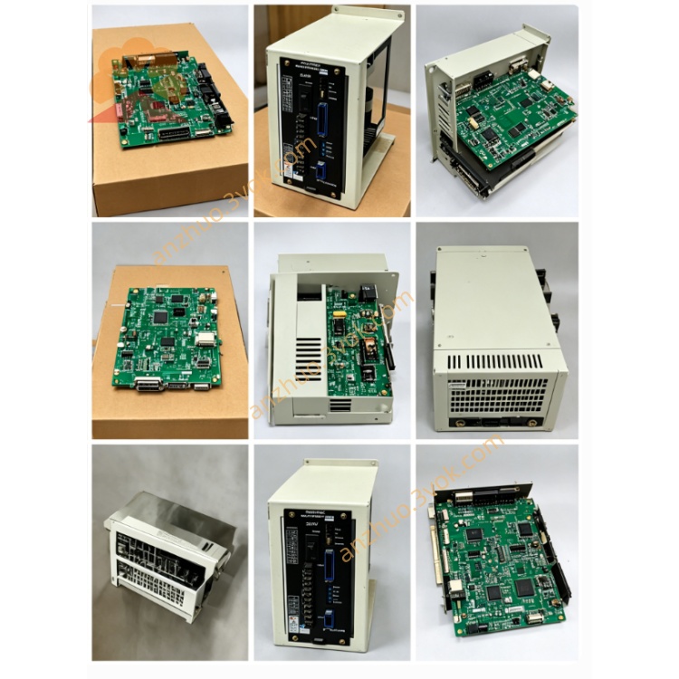
JANCD-YIF01
Description
1.1 Basic Information
Manufacturer: Yaskawa Electric (Japan)
Model classification:
JANCD-YIF01-1E: Core axis interface for DX100 robot controller
JANCD-YIF01-4E: Core axis interface for DX200 robot controller
Position: Mandatory core board installed on YBB backplane (YBB01 for DX100 / YBB21 for DX200), paired with main CPU board (YCP01-E for DX100 / YCP21-E for DX200)
Core Definition: Robot Servo Axis Interface Mainboard, the exclusive high-speed communication bridge between main CPU and all servo drive units inside robot cabinet
1.2 Core Main Functions
High-speed serial bus communication between main CPU(YCP series) and each servo amplifier(SRDA series); transmit motion command, position loop data, speed loop instruction in real time
Collect servo feedback data: actual motor position, motor current, servo fault codes, overheat, encoder abnormal signal, feed back to main CPU for operation judgment and alarm display
Process robot brake control signal, output servo enable, brake release instruction to each axis drive module
Transmit safety chain signal from YSF safety board to servo system, execute emergency stop, servo cutoff protection
Distribute system DC24V control power for internal servo peripheral circuits
2. Electrical & Environmental Specifications
2.1 Power Parameter
Working power supply: DC24V ±10% supplied directly from cabinet backplane slot
Typical power consumption: 18W~23W
Onboard built-in slow-blow fuse: 2A 250V for onboard peripheral circuit protection
2.2 Ambient Working Condition
Operating ambient temperature: -10℃ ~ +55℃
Storage temperature: -25℃ ~ +70℃
Relative humidity: 30%~80%RH, non-condensing; no corrosive gas, conductive dust, welding spatter or strong high-frequency electromagnetic interference
Cooling method: Passive natural air cooling, no built-in cooling fan
2.3 Communication Parameter
Servo communication: Yaskawa proprietary high-speed differential serial bus, real-time cycle ≤250μs per axis
Max supported axis quantity:
YIF01-1E(DX100): Max 8 servo axes
YIF01-4E(DX200): Max 12 servo axes
3. On-board Connector Definition
CN100: Backplane Bus Connector
CN101~CN104: Servo Bus Output Ports (High-speed serial to servo drive)
Differential signal shielded cable connection to each SRDA servo amplifier inside cabinet
CN101: Axis1~Axis3 servo bus
CN102: Axis4~Axis6 servo bus
CN103: Axis7~Axis9 servo bus
CN104: Axis10~Axis12 servo bus (only available on YIF01-4E DX200 version)
CN105: Safety Signal Interface
CN106: Brake Control Common Terminal
4. LED Status Indicator Description
PWR(Green): Power indicator
ON: DC24V input normal; OFF: Fuse blown or backplane power abnormal
RUN(Green): System communication running lamp
Slow flashing: Normal communication with main CPU and all servo drives; Always OFF: Backplane bus fault or CPU communication lost
SERVO(Red): Servo system fault lamp
Steady ON: At least one servo drive communication break / servo alarm; Flash: Partial axis bus short-circuit or cable open circuit
SAFE(Yellow): Safety chain status lamp
ON: Safety loop closed, servo allowed to enable; OFF: E-stop pressed or cabinet safety door open, safety chain broken
5. DIP Switch Setting (S1 On PCB)
No station address setting required (fixed core system board, address solidified inside controller firmware)
BIT1: Servo bus terminal resistance setting: ON=enable terminal resistance (used when last servo on bus), OFF=disable
BIT2~BIT4: Reserved factory setting, keep default OFF position, no modification allowed
6. Standard Installation Steps
Step1 Pre-operation Safety
Step2 Board Insertion
Step3 Servo Cable Wiring
Step4 Power On Confirmation
7. System Software Configuration
8. Common Troubleshooting
Fault 1: PWR LED always OFF
Check onboard 2A fuse burnout, replace with same specification fuse
Re-seat YIF01 board; test DC24V output of corresponding backplane slot
Fault2 RUN LED OFF, PWR normal
Poor contact between YIF01 and backplane gold finger, wipe gold finger with dry alcohol cloth and reinsert
Check main YCP CPU board working status
Fault3 SERVO RED LED steady ON, partial axis alarm
Inspect corresponding CN servo bus cable open/short-circuit, replace damaged shield wire
Check failed axis servo amplifier power supply status
Fault4 SAFE lamp OFF, servo cannot turn ON
9. Version Matching Table
| Model | Matched Controller | Matched CPU | Matched Backplane |
|---|---|---|---|
| YIF01-1E | DX100 | JANCD-YCP01-A/E | YBB01 |
| YIF01-4E | DX200 | JANCD-YCP21-E | YBB21 |
10. Maintenance Precautions
All disassembly, wiring work must be completed under full power-off state
Every 6-month regular maintenance: Clean PCB surface dust, check connector terminals looseness and cable aging
For faulty board: Integral replacement recommended; non-professional disassembly of onboard components is prohibited
Get a Quote