JANCD-YEW01
Description
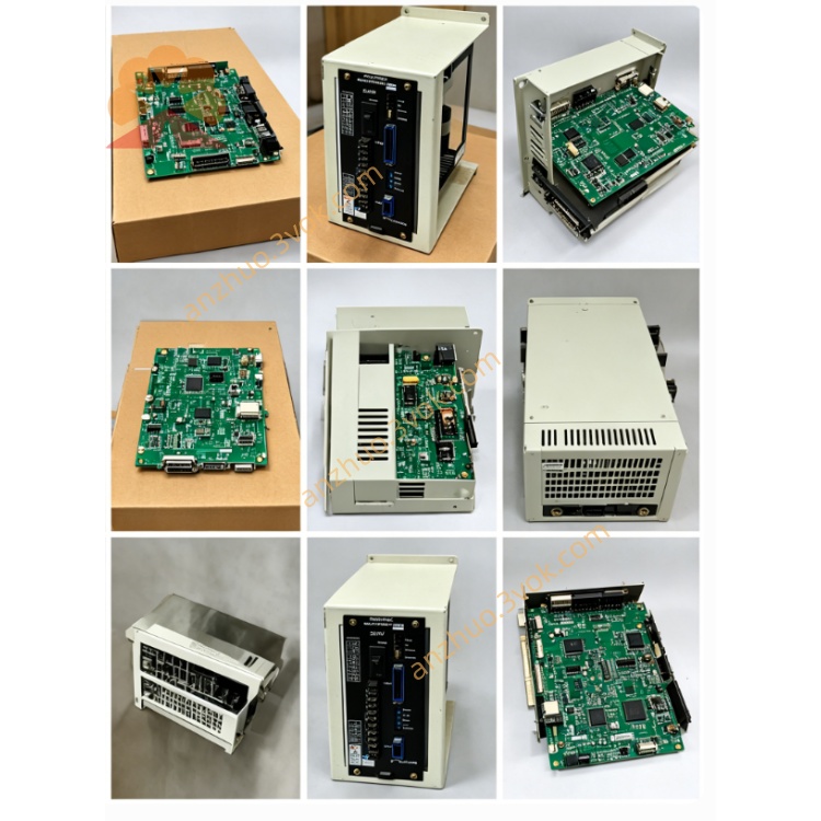
1.1 Basic Description
1.2 System Matching Configuration
Main CPU: JANCD-YCP21-E (DX200 main control board)
Safety Board: JANCD-YSF21-E
Backplane: YBB21 DX200 rack
Install position: free option slot on YBB21 backplane inside DX200 control cabinet
Incompatible: DX100 controller (DX100 uses YEW series for older racks)
1.3 Core Functions
2CH analog output: Output analog command voltage to welder for preset welding current/voltage
2CH analog input: Receive analog feedback signal of actual welding current/voltage from welder
Multi-channel digital contact I/O: Welder ready, arc ON/OFF, gas shortage, wire break, cooling fault, welding completion signal
Wire stick detection dedicated input: Detect electrode short-circuit stick fault during welding
Starting point search output: Analog trigger output for arc seam search sensor (CN321 port)
2. Hardware Electrical Specifications
2.1 Analog Parameter Specification
| Item | Parameter Value |
|---|---|
| Analog Output Channel | 2CH D/A, output range: -5V ~ +5VDC |
| Analog Input Channel | 2CH A/D, input range: -5V ~ +5VDC |
| A/D & D/A Resolution | 16-bit digital conversion |
| Single LSB Value | Approx. 153μV |
| Full Scale Error | ±0.5%FS; Linearity error ≤±5LSB |
| A/D Conversion Cycle | 2ms per channel, max conversion time 60μs |
| Analog Input Impedance | ≥1MΩ |
| Wiring Requirement | Shielded twisted pair 24~28AWG, minimize cable length |
2.2 Digital Contact I/O Spec
Digital Input: 8-point DC24V sink/source compatible, input rated current 5mA MAX
Digital Output: Relay contact output, rated load DC24V/0.5A per point
Wire Stick Detection: 1 dedicated isolated digital input terminal
2.3 Power & Environment Spec
Board operating power: DC24V ±10% supplied from DX200 backplane slot
Fuse: F1/F2 fast acting fuse 1A/250V (Littelfuse 217001 standard part)
Operating ambient temperature: -10℃ ~ +55℃
Storage temperature: -20℃ ~ +70℃
Ambient humidity: 30%~80%RH non-condensing; avoid dew, corrosive gas, heavy dust, strong electromagnetic interference
Cooling mode: Passive natural cooling (no built-in fan)
3. On-board Connector Definition
CN320: Backplane Bus Connector
CN321: Starting Point Detection Output
CN322: Main Welder Interface Terminal (Core port for welder wiring)
Analog Output 1: Welding Voltage Command Output (-5~+5V)
Analog Output 2: Wire Feed Speed / Welding Current Command Output (-5~+5V)
Analog Input 1: Actual Welding Voltage Feedback from Welder
Analog Input 2: Actual Welding Current Feedback from Welder
Digital Input Signals: Gas shortage alarm, wire cut fault, welder ready signal, cooling water abnormal
Digital Output Signals: Arc ON trigger, shielding gas valve output, wire feed enable, welding finish reset
Wire stick detection dedicated input terminal
CN323 / CN324: Auxiliary 24VDC Power Terminal
4. DIP Switch Setting Instruction (S1 Switch on PCB)
4.1 Switch Purpose
Switch BIT 1~BIT4: Binary coding for station No. setting (factory default: Station No.01)
BIT5: Analog output polarity selection (ON=invert output voltage, OFF=standard polarity -5~+5V)
BIT6: Wire detection input logic selection (ON=active high, OFF=active low DC24V)
Mandatory: Set all DIP switches before board installation with cabinet full power OFF.
5. Standard Installation Procedure
Step 1: Safety Pre-operation
Cut off DX200 main AC power, wait minimum 15min for internal main capacitor full discharge to avoid electric shock and board burnout.
Open DX200 cabinet front door, confirm all internal voltage is zero with multimeter test.
Step 2: Pre-set DIP Switch
Step3: Board Insertion
Step4: External Cable Wiring
Use shielded twisted cable for CN322 analog signal wiring, single-point ground for shielding layer at cabinet grounding bar only.
Connect welder control cable between CN322 and analog welder terminal block per welder manufacturer wiring diagram.
Connect seam search sensor cable to CN321 if tracking function is equipped.
Step5: Cabinet Close & Power-on Check
6. DX200 System Software Setting
6.1 I/O Module Configuration
Enter DX200 teach pendant: [SYSTEM]-[OPTION]-[HARDWARE CONFIGURATION]
Activate YEW01-E welding option module with preset station address matching S1 switch setting
Save parameter, reboot controller for configuration to take effect.
6.2 Welding Parameter Setup
Enter welding menu: [ARC WELD SETUP], select analog welder control mode
Calibrate D/A output gain/offset for voltage/current analog output to match welder input specification
Calibrate A/D input feedback coefficient for actual current/voltage feedback correction
7. LED Status Indicator Definition
PWR LED(Green): ON=24V board power normal; OFF=power supply/fuse open circuit
RUN LED(Green): Slow flash=normal data communication with main CPU; steady OFF=bus communication fault
ERR LED(Red): ON=analog channel overvoltage/short or digital I/O short-circuit fault; flash=station address conflict error
8. Troubleshooting Guide
Fault 1: PWR LED OFF
Check F1/F2 1A fuse blowout, replace same specification Littelfuse fuse if damaged
Re-seat YEW01-E board to fix poor backplane contact; test rack slot DC24V output voltage.
Fault2: RUN LED OFF, ERR ON
Recheck S1 DIP station address setting for duplicate address conflict
Verify JANCD-YCP21 main CPU normal operation; check other system boards status.
Fault3: Welder cannot receive analog command voltage
Check CN322 analog output wiring open/short circuit, test D/A output voltage via multimeter
Re-calibrate analog output offset/gain inside DX200 welding parameter menu.
Fault4: No actual current/voltage feedback from welder
Check welder analog feedback output wiring polarity and shield grounding
Confirm A/D input range matches welder signal output specification (-5~+5V).
Fault5: Wire stick detection always triggered
9. Maintenance & Safety Notes
CAUTION: All wiring/board replacement must be done under complete cabinet power OFF state.
Periodic maintenance (every 6 months): Clean PCB dust with dry lint-free cloth, check connector terminal looseness and cable insulation aging.
Prohibited: Modify onboard circuit components or replace non-standard fuse; faulty board requires full unit replacement (no field component repair).
Ambient prohibition: Install away from welding arc spatter, strong high-frequency magnetic field, water vapor and chemical corrosive gas.
10. Related Model Distinction
JANCD-YEW01-E: Standard analog welder interface for single analog welding source (DX200)
Digital welder uses optional digital communication board instead of YEW01-E (WELDCOM network option)
Get a Quote