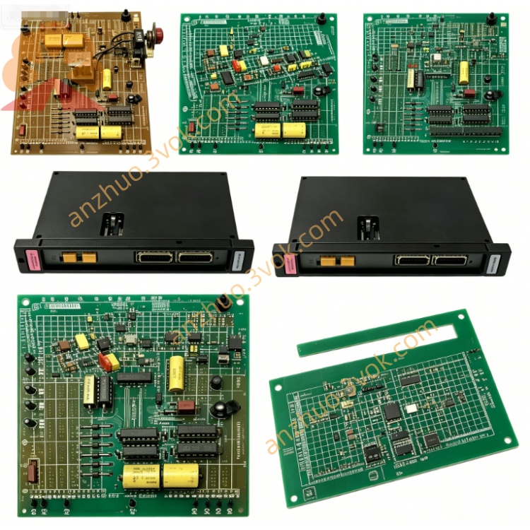
Reliance 57C-424( Electric / ABB AutoMax)
Description
Product Brief Introduction
Model Definition
57C: Represents the AutoMax 57C series rack-mounted hardware platform.
424: Core function code for MaxPak III high-speed link communication module.
No suffix letter indicates standard hardware revision with baseline communication and diagnostic capabilities.
Technical Specifications
Power Supply: 5V DC from backplane, typical operating current 550mA.
Communication Rate: 41.6 Kbaud for MaxPak III link data transmission.
Memory: Onboard dual-port memory for data buffering and status storage.
Operating Temperature: 0°C to 60°C.
Storage Temperature: -20°C to 70°C.
Humidity: 5% to 95% non-condensing.
Protection: Hardware watchdog, overvoltage and overcurrent protection.
Indicators: Front-panel LEDs for POWER, RUN, FAULT, and COMM status; two thumbwheel switches for 1st and 2nd drop number configuration.
Interface and Communication Configuration
Backplane Interface: Gold finger connection to AutoMax Multibus backplane for data interaction with rack CPU and other modules.
MaxPak III Link Port: Dedicated high-speed link interface for connection to MaxPak III drive systems via shielded cables.
Gateway Port: 25-pin female D-Sub RS-232 gateway communication port for external device connection and diagnostics.
**No native fieldbus interface; upper network access requires additional 57C series communication modules.
Core Functions
High-Speed Drive Communication: Transmits real-time motion control commands and receives drive status data between AutoMax rack and MaxPak III drives.
Data Buffering and Synchronization: Uses dual-port memory to buffer and synchronize sequencing, regulation, and status information.
Drive Command Execution: Supports three basic MaxPak III drive commands: change mode request, configuration request, and update request.
Fault Monitoring and Display: Continuously monitors communication link and drive status; displays fault codes via LEDs and digital indicators for quick diagnostics.
Drop Number Configuration: Allows setting of 1st and 2nd drop addresses via thumbwheels for network node identification.
Application Scenarios
Motion Control Systems: Coordinated drive control in packaging lines, textile processing equipment, and automated material handling systems.
MaxPak III Drive Integration: Interface between AutoMax controllers and MaxPak III AC/DC drive systems in manufacturing and process industries.
Legacy Equipment Renovation: Replacement of outdated communication modules in aging AutoMax-based production lines, especially in automotive, rubber, and plastics processing.
Distributed Motion Networks: Multi-drive coordination in printing machinery, metalworking equipment, and industrial cranes.
Operation and Maintenance Instructions
Installation: Power off the rack before insertion/removal; align guides, fully insert gold fingers, and tighten front panel screws to ensure stable contact.
Wiring: Use shielded cables for all external connections; separate signal cables from high-power cables to minimize interference.
Maintenance: Clean dust with dry compressed air every 3–6 months; avoid liquid cleaners on the circuit board.
Troubleshooting: Check LED status, backplane connection, external wiring, and RS-232 gateway diagnostics in sequence; verify drop number settings via thumbwheels.
Storage: Keep spare modules in dry, constant-temperature environment away from corrosive gases and strong electromagnetic interference.
Prohibition: Unauthorized disassembly or modification of onboard components is strictly prohibited.
Get a Quote