
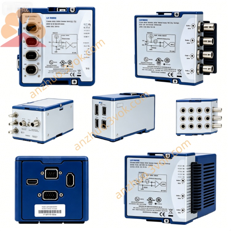
NI USB‑6009 Low-Cost Multifunction CompactDAQ USB DAQ Device
Description
Product Introduction
The NI USB-6009 is an entry-level USB bus-powered multi-functional data acquisition device. It integrates analog input, analog output, digital input/output, and counter functions. The overall structure is compact and plug-and-play, requiring no external power supply. This device is targeted at basic measurement and simple control scenarios. It is easy to operate and offers good value for money. It has been discontinued and is mainly used in teaching experiments, on-site simple monitoring, and the setup of small testing systems.
Model Interpretation
"USB" indicates that the device uses the USB 2.0 interface, responsible for data transmission and overall power supply. "6009" belongs to the NI entry-level multi-functional data acquisition series numbering, corresponding to this 14-bit precision, multi-functional I/O integrated basic acquisition device. Technical Specifications
The analog input supports 8 single-ended channels or 4 differential channels. The analog-to-digital converter has a resolution of 14 bits, and the overall maximum sampling rate of the device is 48 kilosamples per second. The single-ended input range is fixed at ±10 volts, while the differential mode provides multiple programmable ranges. The input circuit has overvoltage protection of ±35 volts. There are 2 analog outputs in total, and the digital-to-analog converter has a resolution of 12 bits. The output voltage range is fixed at 0 to 5 volts. In software timing mode, the update rate is 150 hertz. There are 12 digital input/output channels, compatible with TTL and CMOS levels. Each channel can be independently configured as an input or output mode. There is a 1-bit 32-bit general-purpose counter built-in, with a maximum counting frequency of 5 megahertz. The device is powered by the USB bus, with a working temperature range of 0 degrees Celsius to 55 degrees Celsius, a storage temperature range of -20 degrees Celsius to 70 degrees Celsius, a relative humidity of 10% to 90%, and no condensation during operation.
Interface and Communication Configuration
The device is equipped with a USB 2.0 Type-B interface for connecting to a computer. After connection, the system can automatically recognize the hardware and install the corresponding drivers. The body has multiple groups of screw terminal blocks, arranged in sections for analog input, analog output, digital channels, analog ground, digital ground, and reference voltage output points. The device is a pure hardware acquisition unit with no additional hardware jumpers. All functions, ranges, and sampling rates are configured through software. It fully supports the NI-DAQmx driver program and can run on mainstream operating systems. It is compatible with common development software such as LabVIEW, C language, and Python, enabling data reading, signal output, and device control.
Core Functions
It integrates multiple signal acquisition and control functions. With just one device, it can complete analog signal acquisition, analog voltage output, digital logic interaction, and pulse counting, meeting basic measurement and control requirements. Powered by the USB bus, it does not require an additional power adapter, making it portable and suitable for mobile measurement and field operations. The wiring terminal design is simple and intuitive, paired with a universal driver, with low learning difficulty, facilitating the rapid setup of a basic acquisition system. The input and output circuits have basic protection capabilities, capable of withstanding common overvoltage and static interference, ensuring the stable operation of the device. It supports software customization of various parameters, flexibly adapting to different types of sensors, switch devices, and small actuators. Applicable scenarios
It is mainly used for teaching experiments in majors such as automation, electronics, and measurement and control in universities, to complete basic data acquisition and control teaching demonstrations. It is suitable for simple data recording and status monitoring of slow-changing analog signals in industrial sites and laboratories. It can be used to build small-scale automated test fixtures to achieve reading of switch signals, logic control of indicator lights and small relays. It can also be used for the early prototype debugging of various electronic devices and embedded products, to complete basic signal interaction and functional verification.
Usage and Maintenance Instructions Instruction Manual
When using, first connect the USB cable between the device and the computer. Wait for the driver installation to complete, and confirm that the device is properly recognized before connecting the wires. Follow the terminal markings to distinguish between analog signals, digital signals, and ground terminals. Avoid misconnection and short-circuiting of the lines. When connecting the analog input channel to the signal, the voltage must not exceed the specified range of the device to prevent damage to the internal circuit. The analog output channel is only suitable for low-speed control scenarios and is not suitable for outputting high-frequency waveform signals. Set the sampling rate, voltage range, and digital channel direction parameters through the accompanying software. After setting, start the acquisition or control task.
Maintenance Instructions
The device should be used and stored in a dry and ventilated environment, away from dust, corrosive gases, and strong electromagnetic interference sources. Regularly check if the connection screws are loose, if the terminal surface is oxidized, and if the insulation layer of the external cables is damaged. If any problems are found, immediately cut off the power supply. Before cleaning the device, disconnect the USB connection. Use a dust-free soft cloth to wipe the casing and connection terminals. Do not use liquid cleaners directly. When the device is idle for a long time, remove all external connections, place the device in a cool and dry place, and avoid heavy objects squeezing and severe impacts. When there is communication or functional abnormalities in the device, first check the connection, cables, and driver status. Non-professionals should not disassemble the internal components of the device.
Get a Quote