
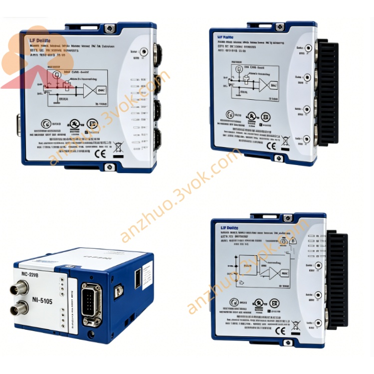
NI SCXI-1192 18 GHz 8-SPDT Latching RF Relay Module
Description
I. Product Introduction
NI SCXI-1192 is an 8-channel 18 GHz SPDT RF relay module for high-frequency and RF signal switching, covering a DC to 18 GHz bandwidth with 50 Ω impedance matching. It features 8 single-pole double-throw (SPDT) latch relays with extremely low insertion loss and high isolation, suitable for microwave, RF communication, and high-speed digital signal routing. It is now discontinued and spare parts and maintenance services are available.
II. Model Interpretation
SCXI: Instrument Signal Conditioning Expansion Series.
1192: Basic model, representing an 8-channel SPDT, 18 GHz high-bandwidth RF switch module.
Component Number: 186676C-04, 776572-92.
Series Positioning: SCXI-1190 (1.3 GHz) → SCXI-1191 (4 GHz) → SCXI-1192 (18 GHz), bandwidth progressively increases.
III. Technical Parameters
Topology: 8 independent SPDT latch relays, each with 1 common terminal and 2 select terminals.
Bandwidth: DC to 18 GHz (-3 dB).
Characteristic Impedance: 50 Ω (RF system standard matching).
Signal Rating: Maximum 30 V (AC/DC), each channel maximum 2 A (DC).
RF Power: 1-3 GHz: 120 W; 3-8 GHz: 80 W; 8-12.4 GHz: 60 W; 12.4-18 GHz: 50 W.
Insertion Loss: ≤ 4 GHz: 0.2 dB; 4-8 GHz: 0.3 dB; 8-12.4 GHz: 0.4 dB; 12.4-18 GHz: 0.5 dB.
Isolation: ≥ 70 dB (channel to channel, 18 GHz).
Relay Life: ≥ 5×10⁶ mechanical actions (no load).
Power Supply: SCXI backplane + 5 V power supply, power consumption approximately 4 W.
Temperature: Operating 0-55 ℃; Storage -40-85 ℃.
Humidity: 5% - 95% without condensation.
IV. Interface and Communication Configuration
Front Panel: 16 SMA RF connectors, corresponding to 8 SPDT relays (each with 1 COM and 2 NO/NC).
Backplane: SCXI standard bus, used for power supply, control instructions, and status readback.
Control Driver: NI-SWITCH driver, supporting development environments such as LabVIEW, C/C++, LabWindows/CVI.
Topology Mode: Fixed 8-SPDT, only supports immediate operation, does not support scanning mode.
Compatibility: Compatible with the full series of SCXI chassis, cannot be routed to the high-voltage analog bus (HVAB).
V. Core Functions
Ultra-high Frequency Signal Switching: 8 independent SPDT, covering DC to 18 GHz, meeting the requirements of microwave, RF, and high-speed digital signal routing.
50 Ω Impedance Matching: Full RF matching throughout, reducing reflection and loss, ensuring high-frequency signal integrity.
Low Loss High Isolation: Low insertion loss in wide frequency band, high channel isolation, suitable for precise RF testing.
Latch Relay Design: State retention without continuous power supply, reducing power consumption and extending relay life.
Independent Channel Control: 8 relays can be individually programmed and controlled, flexible configuration of signal paths.
VI. Application Scenarios
RF/Microwave Testing: 5G, radar, satellite communication, RF devices (filters, amplifiers), high-frequency signal switching and routing. High-speed digital testing: Selection and monitoring of 10 Gbps and above high-speed clock and pulse signals.
Multi-channel RF scanning: ATE system that requires polling of 8 high-frequency signals and switching to different paths.
Research and defense: Laboratory high-frequency signal distribution, maintenance and calibration of military RF equipment.
Mixed-signal system: Combined with other modules of SCXI to construct a low-frequency / high-frequency / RF mixed test system.
VII. Usage and Maintenance Instructions Instruction Manual
Power-off installation: Insert the free slot in the SCXI chassis, tighten the fixing screws, and ensure the backplane bus is securely connected.
RF wiring: Use 50 Ω coaxial cable with SMA connector. Avoid excessive force; for unused ports, it is recommended to connect 50 Ω termination load to reduce reflection.
Software configuration: Install the NI-SWITCH driver, call the niSwitch function to configure the 8-SPDT topology, and control the relay on/off.
Power limit: Strictly follow the maximum power limit for each frequency band to avoid damage to the relay due to excessive power input.
Prohibit hot swapping: Inserting or removing modules or RF cables while powered on is likely to cause damage to the relay, short circuit of the signal, or reflection of RF energy damaging the signal source.
Maintenance instructions
Environment: Maintain ventilation and dryness, temperature 0-55 ℃, away from strong electromagnetic interference, dust, and corrosive gases.
Regular inspection: Monthly check for any looseness, oxidation, or damage of the SMA connector, and check for aging, bending of the coaxial cable.
Cleaning: Wipe the connectors and panel with isopropyl alcohol to avoid liquid entering the module interior; strictly prohibit corrosive cleaners.
Troubleshooting: When there is abnormal signal, prioritize checking RF connection, termination load, driver configuration, and relay status; module failures are mostly due to relay aging or poor contact.
Long-term storage: After power-off, remove the module, clean the connectors, put on a protective cap, and store in an anti-static bag in a cool and dry place.
Get a Quote