
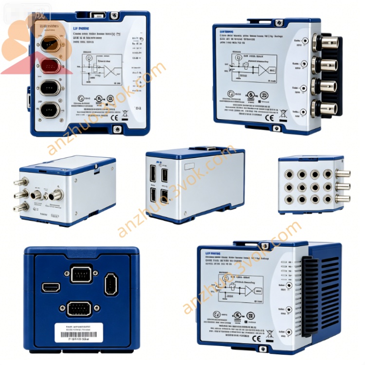
NI SCXI-1140 8-Channel Isolated Analog Input Module
Description
I. Product Introduction
NI SCXI-1140 is a 8-channel synchronous sampling differential signal conditioning module of the SCXI series. It integrates an instrumentation amplifier, sampling hold circuit, low-pass filter, and power frequency notch filter functions. It supports differential or single-ended signal input. The module features electrical isolation and overvoltage protection. It can precisely amplify and suppress noise for weak signals such as thermocouples, strain gauges, and millivolt-level sensors. It is suitable for testing scenarios with high requirements for channel timing consistency. This model has been discontinued in production but still offers maintenance services. Alternatively, inventory and second-hand equipment can be selected for continued use.
II. Model Interpretation
SCXI represents the instrument signal conditioning expansion series. 1140 is an exclusive model of this series, corresponding to an 8-channel synchronous sampling amplification and conditioning module. There is no additional suffix to distinguish versions. The standard component number of the product follows the unified coding system of the series.
III. Technical Parameters
The module supports eight differential inputs and can be configured as sixteen single-ended input modes. The onboard dip switch is fixed to set the gain level, which can be selected as one times, ten times, one hundred times, two hundred times, three hundred times, five hundred times, six hundred times, seven hundred times, and eight hundred times. The maximum input voltage range is positive and negative ten volts. The differential input impedance is not less than one hundred megohms. The common-mode rejection ratio in the DC to one-hundred-hertz frequency band is greater than one decibel. All channels can achieve synchronous sampling hold. The maximum scanning rate of the system is one hundred thousand samples per second. The small-signal bandwidth can reach ten megahertz. An integrated three-pole one-hertz low-pass filter is built-in. Meanwhile, the software can select fifty-hertz or sixty-hertz power frequency notch function. The module has positive and negative thirty volts power-on overvoltage protection. The channel and the chassis can withstand a continuous isolation voltage of two hundred and fifty volts with an effective value, complying with CAT II safety standards. The module is powered by the SCXI chassis backplane, and the overall power consumption is approximately one point five watts. The standard operating temperature range is zero degrees Celsius to fifty-five degrees Celsius. The device calibration parameters are stored in the onboard non-volatile memory. The entire machine has a standard SCXI module structure.
IV. Interface and Communication Configuration
The module's front side is equipped with a fifty-pin DIN connector for external wiring terminals. It is commonly used in combination with SCXI-1301 universal terminals or SCXI-1304 AC/DC coupled terminals. The back side is connected to the SCXI chassis backplane bus, relying on the bus to complete power supply, data transmission, and synchronous timing of multiple modules. The module is reserved for an external TTL trigger interface, which can be connected to external signals for multi-module synchronous sampling. The device has no independent communication interface. It relies on the SCXI bus to establish communication with the backend DAQ equipment. It is compatible with NI-DAQmx driver software for parameter configuration, signal acquisition, and function control. It can be compatible with mainstream development environments such as LabVIEW.
V. Core Functions
It has the ability of eight-channel synchronous sampling. All channel signals can be simultaneously locked, and there is no time deviation between channels, meeting the precise measurement requirements for phase and timing. The multi-level fixed gain design can amplify millivolt-level weak signals specifically, suitable for various low-level sensor outputs. The integrated low-pass filter and power frequency notch circuit effectively filter out high-frequency noise and industrial power frequency interference, improving the stability of measurement data. Electrical isolation is set between the channel and the chassis, and an overvoltage protection circuit is combined. It can resist on-site electromagnetic interference and prevent surge voltage from damaging the backend acquisition equipment. It supports differential and single-ended input modes. By combining different terminals, the application scope can be expanded. Multi-module cascading can also flexibly expand the total acquisition channel number of the system.
VI. Application Scenarios
It is suitable for synchronous temperature sampling of various thermocouples, combined with external terminals to complete cold junction compensation, and for temperature monitoring of industrial furnaces, pipelines, and environmental test equipment. It can be connected to strain gauges, force sensors, and weighing sensors to complete tests such as structural stress and material mechanical properties. For low-level voltage signals output by photoelectric sensors and bioelectric sensors, precise signal conditioning and data acquisition are carried out. It is widely used for multi-channel synchronous testing of mechanical vibration and noise in mechanical equipment, as well as equipment fault diagnosis and structural modal analysis. It can also be applied to multi-channel analog process monitoring in industrial environments with strong interference.
VII. Usage and Maintenance Instructions
Usage Instructions
When adjusting the onboard gain potentiometer switch, the SCXI chassis power supply must be cut off first, and the position setting completed before powering on and running. When installing modules, disconnect the power supply, insert the module into the chassis slot, and tighten the fixing screws. When cascading multiple modules, plan the addresses uniformly to avoid address conflicts. Select the corresponding terminal block according to the signal type, ensure the wiring is firm and neat, and distinguish AC and DC signal circuits. When using the external trigger function, correctly connect the TTL trigger signal to ensure synchronous sampling timing when multiple modules are sampled. The entire system is connected to the SCXI chassis and DAQ equipment through standard cables. In the accompanying software, enable filtering, notch filtering functions, and set the sampling rate reasonably.
Maintenance Instructions
Maintain the usage environment with good ventilation and dryness, away from strong electromagnetic radiation, severe vibration, and high-temperature heat sources. Regularly check the wiring terminals, connectors, and external cables for any looseness, oxidation, or damaged outer skin issues. Clean the module surface dust promptly to ensure heat dissipation. The equipment uses factory-specified calibrated parameters. For long-term high-precision use, it is recommended to conduct a complete machine recheck and calibration once a year. When significant noise or fluctuations are detected in the collected data, check the filtering parameters, grounding status, and line shielding effect; when there are abnormal signals or no data, sequentially troubleshoot module installation, bus connection, trigger lines, and driver configuration. Before the equipment is left unused for a long time, disconnect all power sources and external lines, clean up, and store it in a cool and dry place.
Get a Quote